 |
|
| How An Abrasive Waterjet Works | ||
| QUESTIONS OR COMMENTS | ||
 |
AUTHOR: | Alicia Jillian J. Hardy |
| E-MAIL: | jillian@mit.edu | |
| COURSE: | 2 | |
| CLASS/YEAR: | 3 | |
MAIN FUNCTIONAL REQUIREMENT: Provide a low-force means of accurately machining a wide variety of materials in two dimensions.
DESIGN PARAMETER: An Abrasive Waterjet Machine
BACKGROUND:
Abrasive waterjets are fairly mew machines, introduced to the
automotive, aerospace, and glass industries in 1982. Waterjets, a precursor to abrasive
jets, were first operated in industry in 1970. Waterjets do not use abrasives and
therefore cannot machine as many materials as abrasive jets can. Abrasive jets can machine
a wide range of materials including composites, glass, ceramics, titanium and hardened
steel. The abrasive used to do the cutting is typically garnet and has a Moh hardness of
6.5-7.5. For comparison, the Moh hardness of diamond is (defined to be) 10.
As a means of replacing the processes of drilling, sawing, broaching, gear cutting, profile milling, plmching, slitting, spline cutting and hlanking, abrasive jets are used to machine materials with remarkable accuracy and quality of finish; abrasive jets are typically advertised to be accurate within +/- 0.005in.
There are many advantages to using an abrasive waterjet to rnachine a piece. Among them are the following:
· Abrasive jets can cut through any material softer than garnet (material it uses to do the cutting, whose Moh hardness is at least 6.5).
· The finish of a piece cut with an abrasive jet is of
high quality and the piece looks as though it had been sandblasted. Often, deburring is
not necessary after a piece has been machined by an abrasive jet.
· No heat is required in the process of machining a piece with an abrasive jet. As a
result, parts from an assembly do not experience structural changes from overheating. ·
There are no toxic wastes given off by abrasive waterjets, and no oils are
necessary in the process of machining.
Historically, the abrasive waterjet has required complex programming and experienced
operators; for this reason, abrasive waterjets have taken time in becoming widely used by
manufacturers, particularly in the automotive and aerospace industries. More
recently, however, operation of the abrasive jet has become significantly easier, and use
of this powerful machine is much more common. The abrasive jet is controlled by a
computer and software enhancements have made it possible for less experienced operators to
machine parts using the abrasive waterjet.
GEOMETRY/STRUCTURE:
EXPLANATION OF HOW IT WORKS/ IS USED:
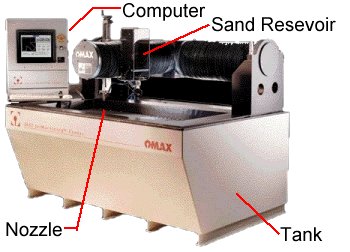
The big picture is that a motor is connected to a piston pump, which pumps fluid through a tube. For a nifty description of piston pumps and a pretty cool picture of one, see reference 2. The fluid is mixed with an abrasive and the mixture comes out of a nozzle aimed at the sheet of material to be machined. Figure la, is a schematic of the basic parts of an abrasive jet, and figure 1b is a photograph of the abrasive jet in building 35 at MIT.
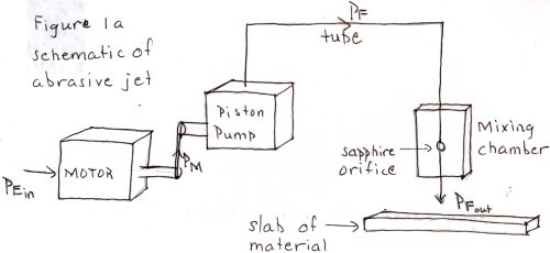 |
| Figure 1a Simplified Schematic of Abrasive Waterjet Machine |
DOMINANT PHYSICS:
Understanding the dominant physics requires a discussion of the flow of power through the
machine. The motor converts electrical power into mechanical power. The motor drives a
piston pump, which converts the mechanical power into fluid power. To describe the
flow of power more quantitatively, the following variables are needed.
| Associated Power | Variable | Description | Units |
|
| Metric | English | |||
| Electrical | I | AC current supplied to the motor | Amps | Amps |
| R | Net resistance of the motor | Ohms | Ohms | |
| V | AC voltage across motor | Volts | Volts | |
| Mechanical | T | Torque produced by the shaft of the motor (connected to pump) | N m | in-lbf |
| w | Angular Speed of the motor shaft | rad/s | rad/s | |
| Fluid | Dp | Pressure difference across the pump | Pa | psi |
| Q | Volume flow rate of fluid | m3/s | in3/s | |
These variables are used to write down expressions for the various forms of power, itemized below.
| Electrical Power | PE | IV / sqrt(2) |
| Mechanical Power | PM | T x w |
| Fuid Power | PF | Dp x Q |
A finer detail is that the motor uses wheels and belts instead of gears and chains; but
because the belts do not slip on the wheels, r1w1
= r2w2, or w1
/w2 = r2/r1.
Looking at the size of one wheel relative to the other is useful in tracking the flow of
power through the connection between the motor and pump. Figure 2a is a schematic of this
connection, and Figure 2b is a cross section of the pulley.
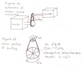 |
| Figure 2a & 2b Schematic of Abrasive Waterjet Motor-Pump Connection |
Flow out, of the pump is turbulent (high Reynold's number) at a pressure on the order of 40,000psi. The fluid enters a ceramic tube, a section of which contains a sapphire orifice. The orifice is made of sapphire because the design specifications require that the orifice remain at a constant, size and shape in spite of the high pressure forces and wear and tear. Sapphire and diamond can both maintain these dimensions for a long period of time, but sapphire is relatively cheap (the assembly containing the saphire orifice can be purchased from OMAX separately for just $39 [see ref 1]). The fluid is forced through the sapphire orifice at a speed on the order of 2500 ft/sec, or about Mach 3. The pressure of the flow at the location of the orifice is lower than atomospheric (increase of fluid speed across the orifice and their is an accompanying pressure drop with the increased fluid velocity). At this point, the abrasive is sucked into the stream of fluid, in what is called a "mixing chamber." See Figure 3 for a cross section of the insides of the mixing chamber and the tubing surrounding the sapphire orifice. Beyond the sapphire orifice, the speed of the fluid-garnet mixture is comparable to the speed of sound (V ~ 740 ft/s). The mixture exits the tube through a nozzle 0.030 inches in diameter at approximately 0.06 inches above the material to be cut.
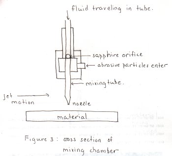 |
| Figure 3 Cross Section of Abrasive Waterjet Mixing Chamber |
The cutting is achieved through a grinding process where a fluid-garnet mixture is used instead of a grinding wheel. Figure 4 is a sketch of the cross-section of a piece of material being machined. The fluid jet drags the abrasive through the material in a curved path as the fluid lags the nozzle. This phenomenon is analogous to what happens when you whirl a rope around in the air; the drag force on the rope causes the rope to lag your hand. Similarly, the fluid lags the moving nozzle, and the mixture can not cut straight through the piece. Because of this fluid lag, it is especially important that the nozzle slow down when turning sharp corners. Machining can go much faster when the edges of pieces are rounded.
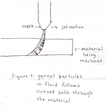 |
| Figure 4 Cross Section of Material Being Machined By An Abrasive Waterjet |
LIMITING PHYSICS:
None Submitted
PLOTS/GRAPHS/TABLES:
None Submitted
WHERE TO FIND ABRASIVE WATEJETS:
None Submitted
REFERENCES/MORE INFORMATION:
References Most of my research was dome on the web at the following sites, listed in order of relevance
3. http://www.itrorn-group.com