User's Guide to the 6.111 C Simulator
- Author:
- Mark W. Eichin
Introduction
The C Simulator is a time domain digital simulator. It is a set of macros
and libraries in the C programming language that can be used to build a
program which simulates the operation of a circuit, which is then compiled
and executed. External inputs and outputs are permitted via the filesystem
(see Chapter "Simulator data files" and the
document [tm:sig]).
Make a copy of the boilerplate simulation file, mysim.c (see
this figure). Also
make a copy of the Makefile which you will find there. Load
mysim.c into your favorite editor (presumably emacs) and
prepare to enter your simulation.
\begin{figure}
\begin{frepcode}{../src/mysim.c}\end{frepcode}
\caption{mysim.c --- Boilerplate Simulation File}
\end{figure}
You should leave the template file unchanged above and below the lines
/* Simulation BEGINS here, type your work BELOW this line */
/* Simulation ENDS here, only type your work ABOVE this line */
These are comments to tell you where your work should go (the C language
begins comments with /* and ends them with */). Everything
outside these lines is the same for all simulations, only the code
pertaining to your circuit goes between these two lines.
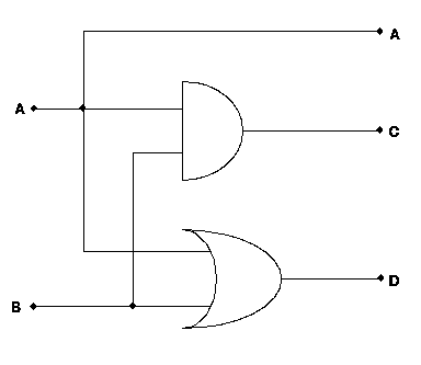
Let's begin with the simple circuit pictured in this figure.
First, trace out each run of wire that is electrically connected.
Insert a declaration
MAKEWIRE(A);
MAKEWIRE(B);
MAKEWIRE(C);
MAKEWIRE(D);
for each run of wire that you have traced out. Record the names (scribbling
them on the schematic might be appropriate) since you will need them later
to actually assemble the circuit. Pick any names you want, but keep in mind
that
- they have to begin with a letter, though they may contain numbers
(they obey the same rules as C identifiers.)
- any wires that are external inputs or outputs should be labelled the
way you want to see them in the input or output files (see
Chapter "Simulator data files" for more details.)
Now that all the wires have been declared, they should be connected to the
circuit. Start by looking up function names for the simulations of each of
the circuit elements. If any of them are not in the predefined table, you
will have to break them down into existing elements, or define a new C
procedure to simulate them (see chapter "Building Submodules".)
Then, using the function for each element, create a connection, as follows:
AND(C, A, B);
OR(D, A, B);
Once connections have been made, output lines should be defined. Since
C and D are interesting, we will output them:
OUTPUT(C);
OUTPUT(D);
And, since the schematic shows A as being carried through to the
output of the circuit, we'll print it as well:
OUTPUT(A);
The input values will be assumed to come from a file automatically. Now that
you have entered these into the file, save it, and exit the editor.
Now type make mysim. This will compile your simulation, and add the
standard simulation libraries to it. If you see messages like\footnote{Bear
in mind that different compilers may generate different messages.}
"mysim.c", line 33: syntax error
"mysim.c":33: syntax error
*** Exit 1
Stop.
then there was some error in what you typed.
Another error you may receive is
mysim.c:33: undeclared variable `D' (first use here)
If `D' is a wire name, perhaps you left out the MAKEWIRE(D)
statement.
Be sure to check the line listed (and lines before it; C may report
errors after they happen, but it will never report them before it
finds them) and the following things:
- Make sure that you have not left out the semicolons after the commands
used. Semicolons separate commands, newlines are ignored.
- Make sure that you have spelled and capitalized the commands
correctly. C is both case and spelling sensitive.
- Make sure that you gave the right arguments to the function (check the
table again if you are not sure.)
- Make sure that the wire name you used was created in advance (with the
MAKEWIRE command). Also be sure that it is spelled correctly.
You may also get an error of the form
Undefined:
_ANND
*** Exit 1
Stop.
The undefined symbol will probably be a misspelled command name.
Check back in mysim.c for that spelling, and correct it. Check in the
table of functions if you are not sure.
Complete user code for simulation
/* Simulation BEGINS here, type your work BELOW this line */
MAKEWIRE(A);
MAKEWIRE(B);
MAKEWIRE(C);
MAKEWIRE(D);
AND(C, A, B);
OR(D, A, B);
OUTPUT(A);
OUTPUT(C);
OUTPUT(D);
/* Simulation ENDS here, only type your work ABOVE this line */
\begin{figure}
\begin{frepcode}{../src/demo.c}
\end{frepcode}
\caption{Raw user template}
\end{figure}
Once you have successfully compiled the simulation (that is, once make runs
through and prints only the compilation commands, and no error messages or
``Stopped'' messages) you can run it. Typing
mysim
by itself will set up the simulation, and process any SETOUTPUT()
statements, and run the simulation, printing the results.
If you want to read an input file into the simulation, use the command
mysim -i filename
where filename contains the input statements (see
Chapter "Simulator data files"). To record the result in a file outputfile,
use the command
mysim -o outputfile
The -o and -i commands may be mixed. You can use the digital
oscilloscope to produce and read the data files.
Building Submodules
Complex submodules should either be
- implemented in C as new functions, or
- implemented as simulator subunits.
New functions are straightforward to implement, and fast as well, if you are
familiar with the internal workings of the simulator. This is currently left
to the technical reference manual, but may be detailed here at a later time.
A simulator subunit can be created by making a copy of mysub.c. If
you are only making one subunit, this will suffice. Follow the same
procedure described in Chapter "How to create a
simulation" to construct the simulation,
using MAKEWIRE for the internal wiring. To create a template function
for the main body of the simulator to use, edit the template line at the top
of the file:
#define FUNCTION my_func
#define MY(OUT, IN1, IN2) make_binop(my_func, OUT, IN1, IN2)
#define DONE
Use your editor's global replace to change all uses of my to
whatever name you want to assign to the function you create. This
should change my_func, MY, and later MY_DELAY to
appropriate names. MY_DELAY is optional, and probably set it
to 1 if your element doesn't use it.
The #define MY(OUT, IN1 ... ) ... statement is what creates
the macro the user calls to link this element into their wirelist.
There are several procedures for creating these:
- make_binop(op, c, a, b) creates a node of circuit element op
that has arguments c, a, and b, but only depends on a and b. This is
used for and, or, xor, delay, and tristate.
- make_unop(op, b, a) creates a node of circuit element op that
has arguments b and a, but only needs to run when a changes. This is
used for the not primitive.
- make_tracer(op, line) creates a node which runs the procedure op
when line changes state. This is used by the output primitive, and as
an obvious way to implement LED's or other indicator devices.
- make_anop(opcount, oparguments, argcount, arguments) is the
generic construction macro with arguments of
- opcount: the number of arguments in the oparguments list. The
valid range is currently 0 through 9.
- oparguments: the list of the arguments that should cause the
procedure to run.
- argcount: the number of arguments in the real arguments list.
The valid range is currently 0 through 10.
- arguments: the real arguments, which are passed as a generic
list to the procedure which is the first element in the list. By
design, the first element of this list must be the procedure
to call to process the circuit changes; by convention, the next
elements are the output lines, followed by the input (driving) lines.
The primitives you should need are either declarations or statements.
The declarations are
- STATE to declare variables that hold the current values of
wires.
- Wire for variables which actually hold wires.
Statements include
- SAVEOUTWIRE(argumentlist, wirename) saves the current wire in the
list of arguments into the wire called wirename (which must be
declared above.) It then advances the argumentlist to the next
argument.
- READNEXTSTATE(argumentlist, statename) saves the state of the
current wire in the list of arguments into the state variable called
statename (which must be declared above.) It also advances the
argumentlist to the next argument.
- READNEXTSTATETIME(argumentlist, statename, timeval) saves the
state of the current wire in the list of arguments into the state
variable called statename (which must be declared above) and the time
at which the change will occur into the variable called timeval. It
also advances the argumentlist to the next argument.
- SETOUTPUT(wirename, statename, timeval) sets the write named wirename
to the value of the state variable called statename at the value of
the time expression timeval. timeval is often in the form
globaltime+MY_DELAY.
- READNEXTTIME(argumentlist, timevariable) saves a time value
from the argument list and stores it into timevariable. It advances
the argumentlist to the next argument. (This is used in the DELAY
primitive, and is included as an example of other argument choices.)
\begin{figure}
\begin{frepcode}{../src/funclib/xor.c}\end{frepcode}
\caption{ xor.c: a sample circuit element extension.}
\end{figure}
Simulator data files
(These file formats are based on those used in
[tm:sig].)
The input file format consists of lines which are either assignments or wait
statements. An assignment consists of a wire name followed by a space and
then a value, which is one of
- Tag
- Meaning
- 1
- Logic High
- 0
- Logic Low
- U
- Undefined
- X
- Tristate
- C
- Contention
A sample file is included in this Figure.
A 0
B 0
wait 50
A 1
wait 10
B 1
wait 40
A 0
wait 50
A 1
wait 10
B 0
wait 40
A 0
wait 100
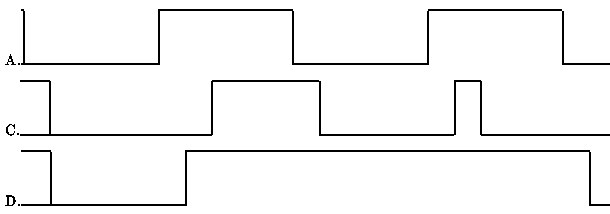
wait 1
A 0
wait 10
C 0
C 0
D 1
D 0
wait 40
A 1
wait 10
C 0
D 1
wait 10
C 1
D 1
wait 30
A 0
wait 10
C 0
D 1
wait 40
A 1
wait 10
C 1
D 1
wait 10
C 0
D 1
wait 30
A 0
wait 10
C 0
D 0
A wait statement is a line containing the token wait either alone or
followed by a number of time units (nominally nanoseconds) before the next
state change. If the number is left out, it means to allow the simulator to
``settle'' before making the next state change. The simulator currently
ignores these statements, as it propagates any non-delayed changes
immediately.
These files can be read in by the C simulator, the Lisp Simulator, or
the Digital Oscilloscope. The Oscilloscope can also build these input
files.
The following table lists the standard circuit elements included with
the C Simulator. Other specific elements may be have been added for
specific projects; see your local documentation for more detail.
- and
- C <- A .AND. B
- or
- C <- A .OR. B
- xor
- C <- A .XOR. B
- and
- C <- A .AND. B
- not
- B <- .NOT. A
- tristate
- if B then C <- A else C <- tristate
- delay
- B <- A after del ticks
- output
- write text value of A with timestamp
The D Flip Flop is a bit more complex, and is simulated in the detail
described below.
Table from page 5-22, TI databook, for 7474:
|------------------------------------------------|
|              INPUTS            |    OUTPUTS    |
|--------------------------------+---------------|
| preset | clear | clock |   D   |   Q   |  Q'   |
|--------+-------+-------+-------+-------+-------|
|   L    |   H   |   X   |   X   |   H   |  L    |
|   H    |   L   |   X   |   X   |   L   |  H    |
|   L    |   L   |   X   |   X   |   H*  |  H*   |
|   H    |   H   |   ^   |   H   |   H   |  L    |
|   H    |   H   |   ^   |   L   |   L   |  H    |
|   H    |   H   |   L   |   X   |   Q0  |  Q'0  |
|--------+-------+-------+-------+-------+-------|
|                                   *unstable.   |
|------------------------------------------------|