SunFire 280R Server
SunFire 280R 4U Server - Pictures taken 2001-07-10 in the MIT W92 machine room. This machine is slated for installation as an Athena dialup server.
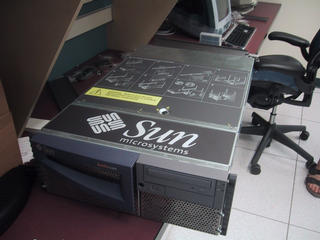 SunFire 280R Server, in the MIT W92 machine room, in preparation for CPU
upgrade and photo essay
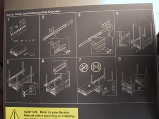 Detailed instructions on top of lid for rack mounting hardware.
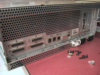 Rear view of 280R. The random bolts on the desk are NOT part of the Sun, but
clutter from some other hardware; most screws and bolts on this machine are
"captive".
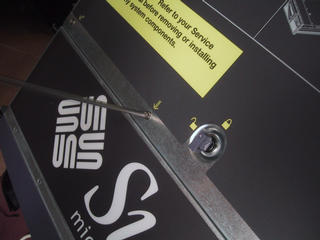 Three captive screws and a tamper key are all that is needed to release the
top lid.
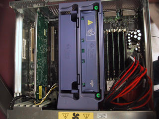 Rear half of 280R. On the left, 5 PCI slots; on the right, 4 memory slots; in the middle, one CPU module and one spacer. The red and black cables are the power supply harness.
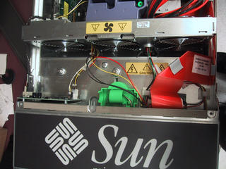 The middle section of the 280R; three fans, one dedicated to the CPU modules. The green plastic clasp holds the "cheap torque wrench" for the CPU units; the red ribbon cable is the IDE bus (connected here to a DVDrom drive.)
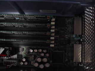 Memory modules.
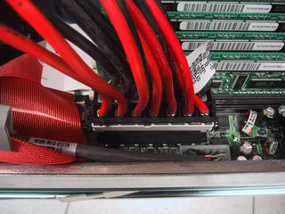 10 gauge wires in power harness; memory modules in the background; IDE ribbon cable on the left.
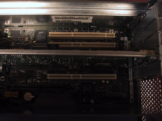 PCI slots.
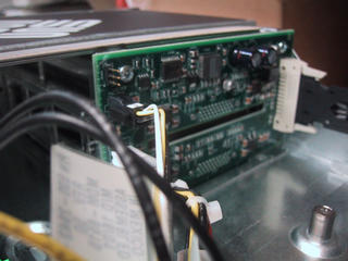 Connector module for SCA/Fibre Channel (FC-AL) drives (two drives.)
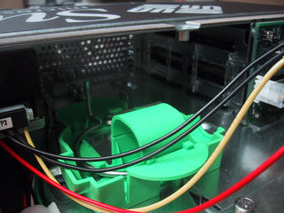 Empty space in front section between drives; plastic clasp holding CPU torque wrench. Power cables for IDE DVDROM drive.
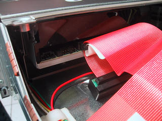 DVDROM drive in place, IDE cable and jumper blocks.
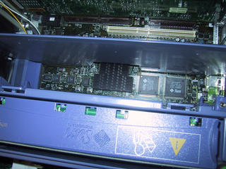 Second CPU slot with spacer removed; first CPU still in place.
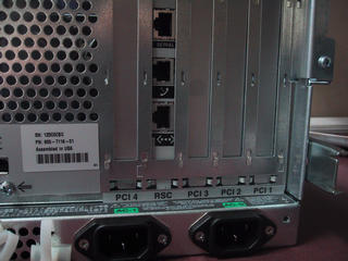 RSC (Remote System Control) card -- which can call out and notify on failure via email or pager; remote power and other LOM-like features. Serial port, phone (56K modem), and ethernet connectors. Also the 4 PCI slots and two power connectors.
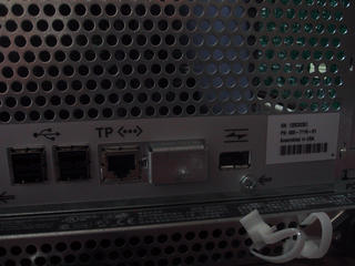 Middle set of connectors - 4 USB, 1 ethernet, one HSSDC-copper-FC-AL (fibre channel over copper.) The blank section looks like it might be for a firewire option.
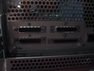 Two serial, one parallel, one scsi.
 One of the CPU screws. Actually supposed to be captive, oops.
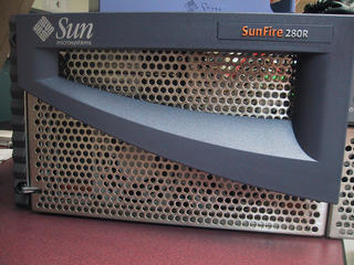 Front left door and plasticwork.
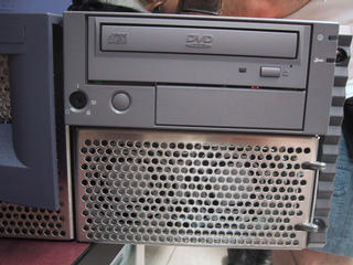 Front right door, DVDROM drive, power switch, power and error (wrench) LEDs, tamper lock, and additional bay (would fit a floppy if anyone used them anymore.)
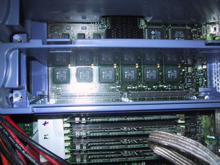 CPU bay with both CPUs removed.
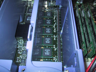 Another view looking down into primary CPU bay.
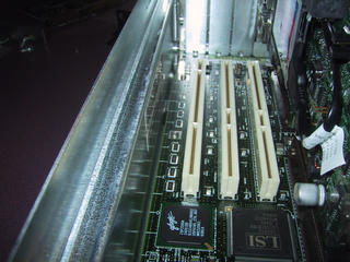 View of 3 of the PCI slots and the RSC card.
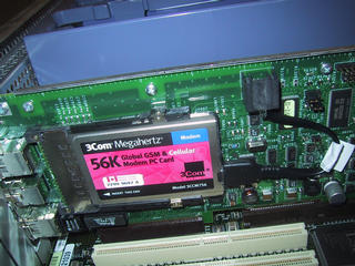 RSC card - note the 3Com 56K PC Card modem.
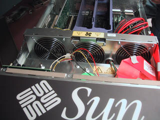 Bank of fans, and empty CPU slots.
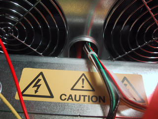 Power passthrough between fans.
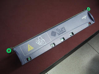 CPU module, by itself; top view. Green circles are the square-drive captive
screws that hold it in place.
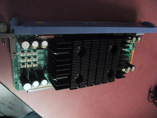 CPU module showing three heat sinks - apparently the central one is over the CPU (thus the bolts) and the left and right ones are over the cache memory chips (and are not mechanically connected to the central one.)
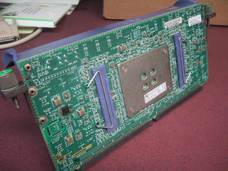 Bottom view of CPU module; note the blue plastic buffers and metal clips for the cache heatsinks, and the metal plate with bolts in the corners for the CPU heatsink. Lots of discrete surface mount components on this side too.
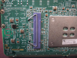 Closeup of heatsink supports, left side.
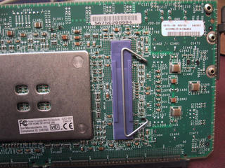 Closeup of heatsink supports, right side.
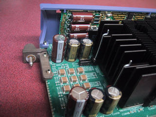 Detail of what appears to be more power control circuitry on underside of plastic shell; note also the embossed "L1" on the left screw bracket.
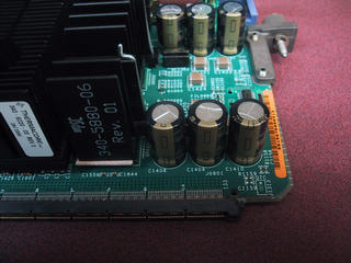 More detail of heatsinks, CPU edge connector, "R2" screw bracket.
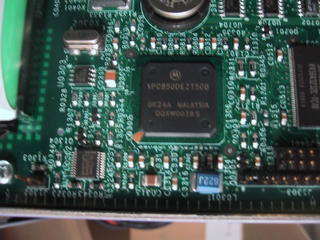 Appears to be a processor (PPC variant, 50mhz, if google is to be believed) on the RSC
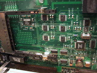 Detail of RSC card with PC Card modem removed.
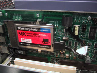 Detail of RSC card with PC Card modem installed; note "dongle" connecting onto the RSC so it can be routed to the back of the machine.
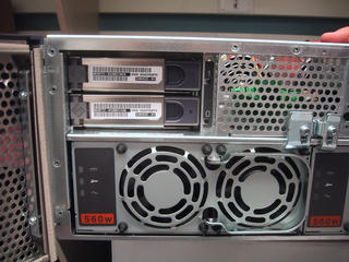 Front left door open, exposing two drives and a power supply module.
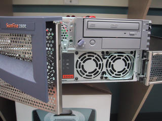 Front right door open, exposing the second power supply module.
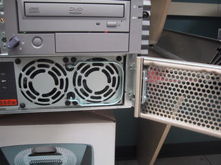 Closer view of right hand power supply module.
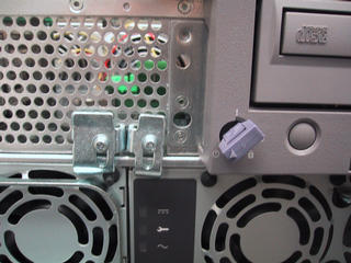 Detail view of captive-screw latches holding power supplies in place individually.
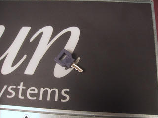 Closeup of the tamper-lock key (not intended for security.)
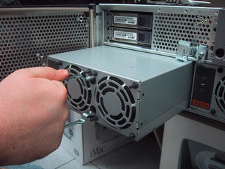 Left power supply, unlatched and being removed using the builtin handle.
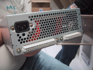 Closeup of power supply system connectors, AC line connector. Note the large isolated hole under the AC connector; this is the entry port for the stabilizing post. (kcr is holding the unit.)
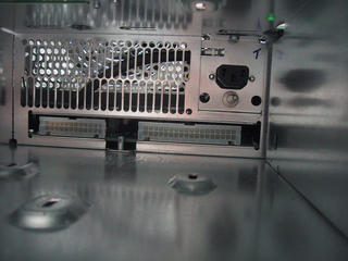 Detail view of empty power supply bay; note stabilizing post. Note also the airflow grille and the fan beyond.
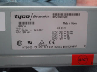 Closeup of power supply specifications: 3.3V/60A, 5V/70A (do not lick), 12V/5A, -12V/0.5A, 5.1V/1.5A.
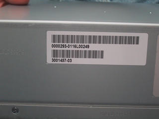 Other labelling on power supply module.
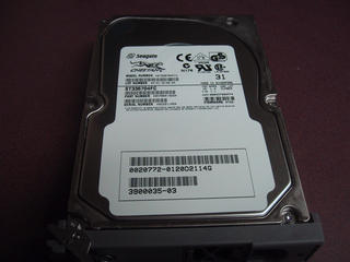 One of the Seagate "Cheetah" drives.
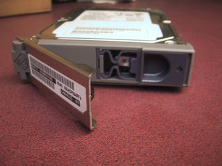 Detail of drive release latch and handle.
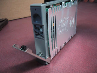 View of drive shell and handle.
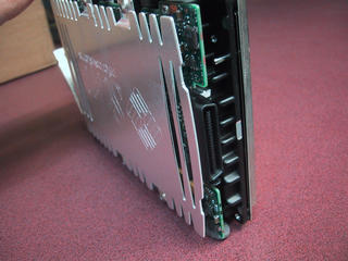 Closeup of FC-AL connector on Cheetah drive.
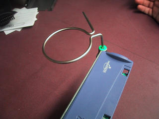 CPU wrench - note that this serves as a torque wrench for tightening the screws by virtue of the tension in the loop.
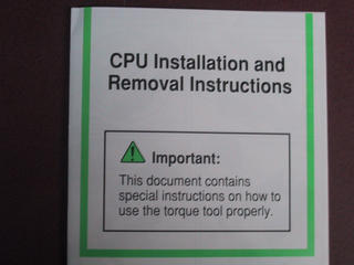 The instructions for removing and installing the CPU modules, which we'd removed and tossed aside because it was in the way. Reading it later was enlightening...
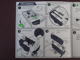 Page 1. Note the emphasis provided by having the bright green plastic be the only color on the page.
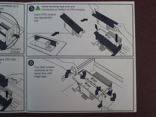 Page 2. Do not lick.
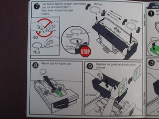 Page 3. Oh, that's an airguide, not a support frame...
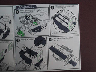 Page 4. And there's a non destructive way to get the instructions out too.
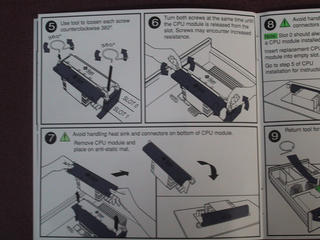 Page 5. Do not lick this time either.
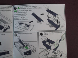 Page 6. And don't drop the wrench in the power supply.
 Back cover. It has a part number, so it must be a part, which is how I justify including it here...
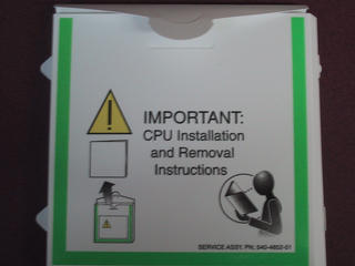 The protective envelope (some plastic-like material) holding the manual in place.
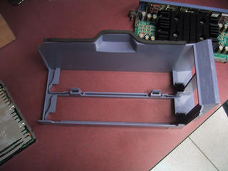 The air guide, seen from underneath; note the weatherstripping (and the CPU module in the background.)
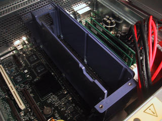 CPU guides without airflow guide, again note PCI slot 4 to the left, and memory modules to the right.
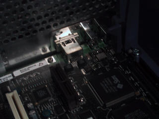 Closeup of HSSDC-copper-FC-AL connector from inside the machine.
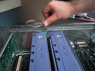 Demonstration of torque wrench tool with both CPU modules in place.
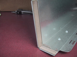 Closeup of edge-shielding on back edges of cover.
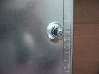 Closeup of tamper/lock latch. Screws are not visible from this side.
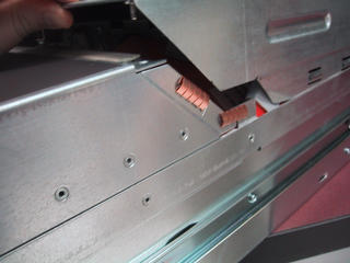 Detail of shielding at front edge of cover.
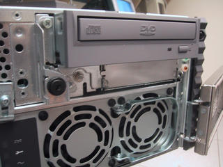 Closeup of DVDROM and (empty) floppy bay.
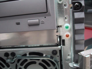 Closeup of power and error (wrench) LED.
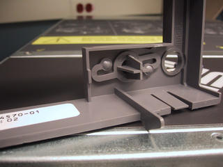 Detail of power-button "spring" on front plasticwork.
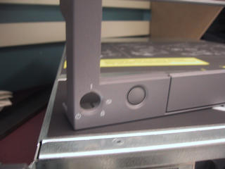 Front view of keyhole and power button on plasticwork.
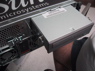 Partly removed DVDROM + floppy assembly; note captive screws.
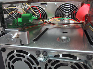 View of empty IDE + floppy bay; note power connectors, big green cpu-wrench clip, fans. Also note power switch.
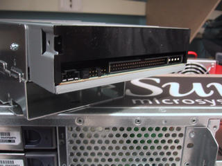 Closeup of DVDROM IDE connector, power, jumpers; note empty bay below for floppy.
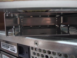 Closeup of (empty) floppy bay from the back, under the DVDROM drive.
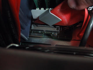 Likely floppy controller connector on mainboard, immediately adjacent to IDE bus connector (red ribbon.) (marc's thumb holding cable out of the way)
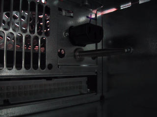 Closeup of power supply alignment spike, showing depth and taper more clearly. Yay small cameras (taken with camera inserted into bay, no mirrors.)
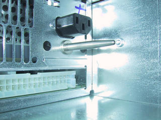 Closeup of power supply alignment spike, taken with flash to bring out details a little more clearly.
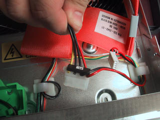 Detail of IDE power connectors; note that 12V supply is not passed through to further connectors which do not need it.
 SunFire 280R Server, in the MIT W92 machine room, in preparation for CPU
upgrade and photo essay
 Detailed instructions on top of lid for rack mounting hardware.
 Rear view of 280R. The random bolts on the desk are NOT part of the Sun, but
clutter from some other hardware; most screws and bolts on this machine are
"captive".
 Three captive screws and a tamper key are all that is needed to release the
top lid.
 Rear half of 280R. On the left, 5 PCI slots; on the right, 4 memory slots; in the middle, one CPU module and one spacer. The red and black cables are the power supply harness.
 The middle section of the 280R; three fans, one dedicated to the CPU modules. The green plastic clasp holds the "cheap torque wrench" for the CPU units; the red ribbon cable is the IDE bus (connected here to a DVDrom drive.)
 Memory modules.
 10 gauge wires in power harness; memory modules in the background; IDE ribbon cable on the left.
 PCI slots.
 Connector module for SCA/Fibre Channel (FC-AL) drives (two drives.)
 Empty space in front section between drives; plastic clasp holding CPU torque wrench. Power cables for IDE DVDROM drive.
 DVDROM drive in place, IDE cable and jumper blocks.
 Second CPU slot with spacer removed; first CPU still in place.
 RSC (Remote System Control) card -- which can call out and notify on failure via email or pager; remote power and other LOM-like features. Serial port, phone (56K modem), and ethernet connectors. Also the 4 PCI slots and two power connectors.
 Middle set of connectors - 4 USB, 1 ethernet, one HSSDC-copper-FC-AL (fibre channel over copper.) The blank section looks like it might be for a firewire option.
 Two serial, one parallel, one scsi.
 One of the CPU screws. Actually supposed to be captive, oops.
 Front left door and plasticwork.
 Front right door, DVDROM drive, power switch, power and error (wrench) LEDs, tamper lock, and additional bay (would fit a floppy if anyone used them anymore.)
 CPU bay with both CPUs removed.
 Another view looking down into primary CPU bay.
 View of 3 of the PCI slots and the RSC card.
 RSC card - note the 3Com 56K PC Card modem.
 Bank of fans, and empty CPU slots.
 Power passthrough between fans.
 CPU module, by itself; top view. Green circles are the square-drive captive
screws that hold it in place.
 CPU module showing three heat sinks - apparently the central one is over the CPU (thus the bolts) and the left and right ones are over the cache memory chips (and are not mechanically connected to the central one.)
 Bottom view of CPU module; note the blue plastic buffers and metal clips for the cache heatsinks, and the metal plate with bolts in the corners for the CPU heatsink. Lots of discrete surface mount components on this side too.
 Closeup of heatsink supports, left side.
 Closeup of heatsink supports, right side.
 Detail of what appears to be more power control circuitry on underside of plastic shell; note also the embossed "L1" on the left screw bracket.
 More detail of heatsinks, CPU edge connector, "R2" screw bracket.
 Appears to be a processor (PPC variant, 50mhz, if google is to be believed) on the RSC
 Detail of RSC card with PC Card modem removed.
 Detail of RSC card with PC Card modem installed; note "dongle" connecting onto the RSC so it can be routed to the back of the machine.
 Front left door open, exposing two drives and a power supply module.
 Front right door open, exposing the second power supply module.
 Closer view of right hand power supply module.
 Detail view of captive-screw latches holding power supplies in place individually.
 Closeup of the tamper-lock key (not intended for security.)
 Left power supply, unlatched and being removed using the builtin handle.
 Closeup of power supply system connectors, AC line connector. Note the large isolated hole under the AC connector; this is the entry port for the stabilizing post. (kcr is holding the unit.)
 Detail view of empty power supply bay; note stabilizing post. Note also the airflow grille and the fan beyond.
 Closeup of power supply specifications: 3.3V/60A, 5V/70A (do not lick), 12V/5A, -12V/0.5A, 5.1V/1.5A.
 Other labelling on power supply module.
 One of the Seagate "Cheetah" drives.
 Detail of drive release latch and handle.
 View of drive shell and handle.
 Closeup of FC-AL connector on Cheetah drive.
 CPU wrench - note that this serves as a torque wrench for tightening the screws by virtue of the tension in the loop.
 The instructions for removing and installing the CPU modules, which we'd removed and tossed aside because it was in the way. Reading it later was enlightening...
 Page 1. Note the emphasis provided by having the bright green plastic be the only color on the page.
 Page 2. Do not lick.
 Page 3. Oh, that's an airguide, not a support frame...
 Page 4. And there's a non destructive way to get the instructions out too.
 Page 5. Do not lick this time either.
 Page 6. And don't drop the wrench in the power supply.
 Back cover. It has a part number, so it must be a part, which is how I justify including it here...
 The protective envelope (some plastic-like material) holding the manual in place.
 The air guide, seen from underneath; note the weatherstripping (and the CPU module in the background.)
 CPU guides without airflow guide, again note PCI slot 4 to the left, and memory modules to the right.
 Closeup of HSSDC-copper-FC-AL connector from inside the machine.
 Demonstration of torque wrench tool with both CPU modules in place.
 Closeup of edge-shielding on back edges of cover.
 Closeup of tamper/lock latch. Screws are not visible from this side.
 Detail of shielding at front edge of cover.
 Closeup of DVDROM and (empty) floppy bay.
 Closeup of power and error (wrench) LED.
 Detail of power-button "spring" on front plasticwork.
 Front view of keyhole and power button on plasticwork.
 Partly removed DVDROM + floppy assembly; note captive screws.
 View of empty IDE + floppy bay; note power connectors, big green cpu-wrench clip, fans. Also note power switch.
 Closeup of DVDROM IDE connector, power, jumpers; note empty bay below for floppy.
 Closeup of (empty) floppy bay from the back, under the DVDROM drive.
 Likely floppy controller connector on mainboard, immediately adjacent to IDE bus connector (red ribbon.) (marc's thumb holding cable out of the way)
 Closeup of power supply alignment spike, showing depth and taper more clearly. Yay small cameras (taken with camera inserted into bay, no mirrors.)
 Closeup of power supply alignment spike, taken with flash to bring out details a little more clearly.
 Detail of IDE power connectors; note that 12V supply is not passed through to further connectors which do not need it.