Phone
+1 857 209 6440
Email
rebei@mit.edu
Autonomous Pneumatic Actuating Gripper For Mobility Assistance
Soft Robotics, PCB Design and Manufacturing, Embedded Programming, and System Design
Summary
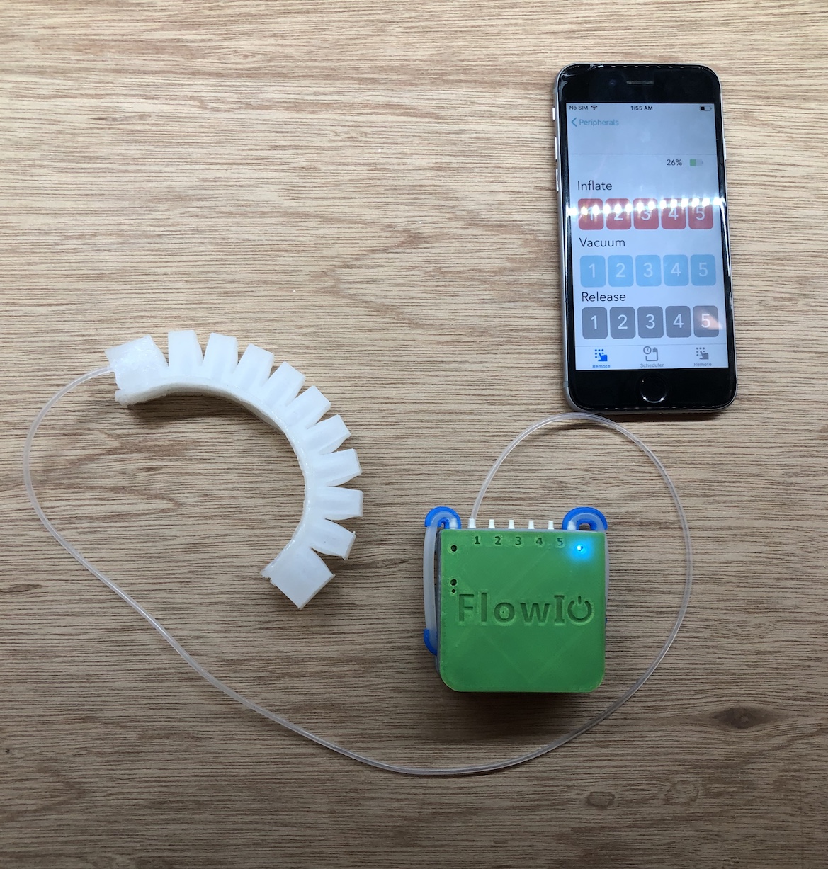
Many types of orthopedic or neuromuscular impairments can impact mobility. Mobility impairments range from lower body impairments, which may require use of canes, walkers, or wheelchairs. In addition, loss of grasping ability, whether caused by injury, disease, or other mechanisms, is a significant problem which negatively impacts quality of life in patients. It is possible to recover some lost function through intensive physical therapy, which typically involves the use of repetitive task practice (RTP). This may result in less freedom in the ability for people to grab objects from locations such as the floor and heigher tables. This is why I created this device with help by the FlowI0 platform developed by Ali Shtarbanov.
After building this device, I examined the effects of air pressure inside of these actuators on the kinematics and curvature of the gripper. You can veiw my research below.
Page Index
Silicone Grippers
Handle Design and Manufacturing
Electronics Design and Production
Programming Board
Electronics and Gripper Housing
System Integration
Final Product
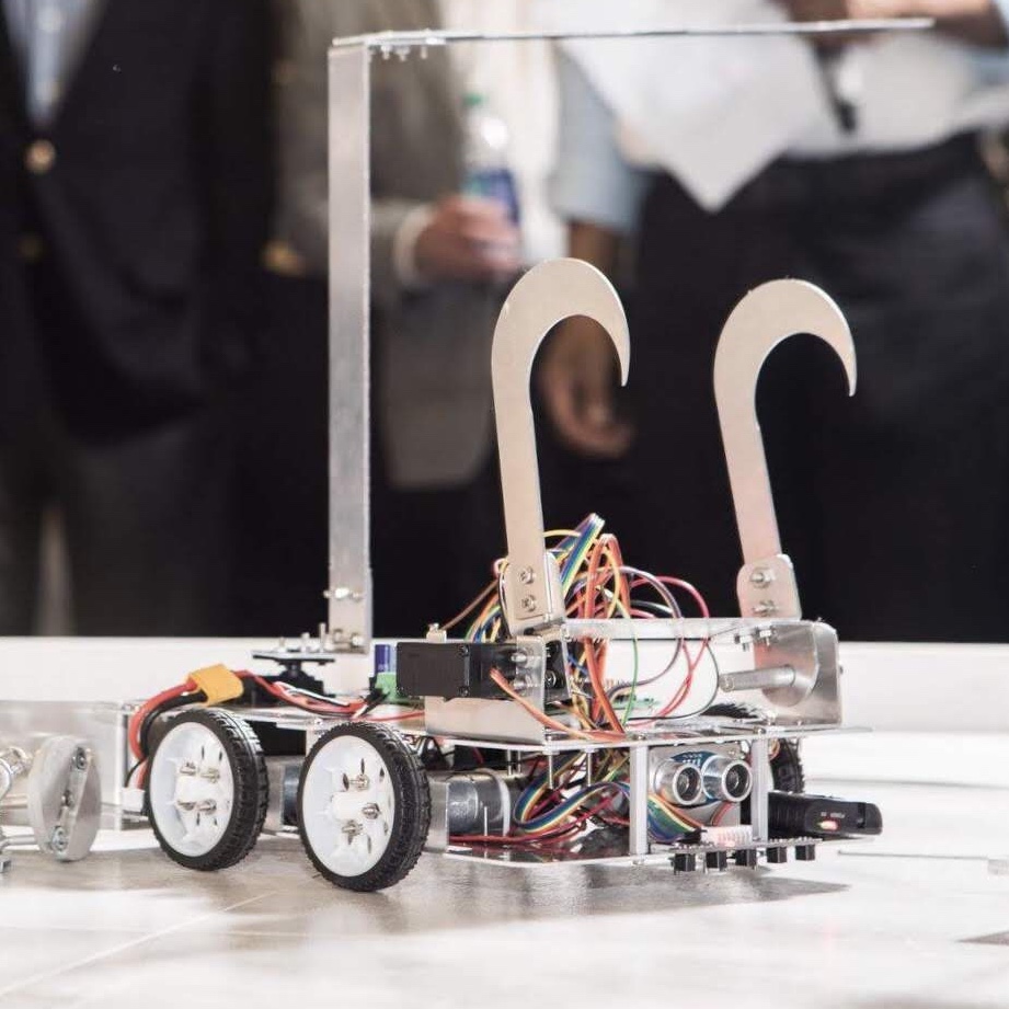
Idea Brainstrom
Silicone Grippers
PneuNets Bending Actuators
The design that I used for the pneumatic bending actuators are actually a modification of a class of soft robotic actuators originally developed by the Whiteside Research Group at Harvard. The grippers are comprised of a series of connected chambers that inflate when pressurized. Attached to the series of chambers is a strain limiting layer, in my case fabric, that allows for the bending motion of the grippers.
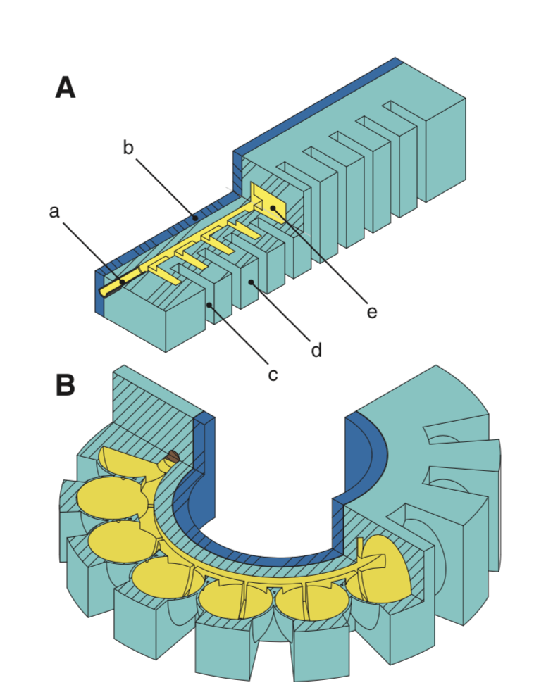
This above image is a rendering of PneuNets Soft Robotic Grippers. The series of connected chambers are shown in yellow, the strain limiting layer is shown in dark blue, and the elastomer is shown in light blue. The left image illustrates the variables in the mold geometry. The right image shows the gripper in its actuated state when the yellow chambers are filled with air.
Introducing various materials in the soft robotic gripper will allow to further control actuator behavior. The Elastic Modulus is a measure of the elastic properties of a solid undergoing tension or compression, also known as the stiffness of a material. A higher modulus means the material is more rigid and typically means that the material is less likely to deform. The strain limiting layer will have a higher elastic Modulus then the elastomer that the rest of the gripper is made of. Because of this, the walls of the chambers will deform when the chambers inflate with air, while the strain limiting layer just bends. However, the Elastic Modulus of the strain limiting layer can’t be high enough to not bend from the compressive forces of the air-filled chambers.
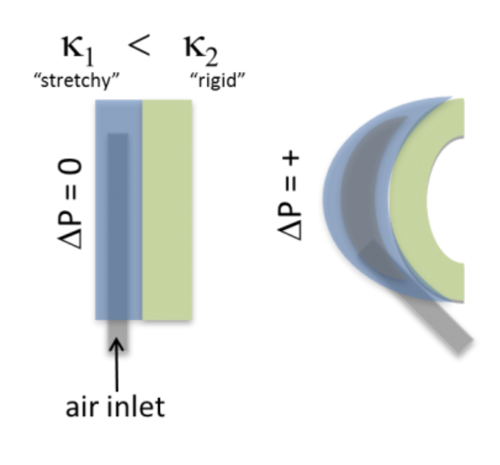
This image illustrates the introduction of a strain limiting layer, shown in green, creates a bending motion of the soft robotic grippers due to the difference in both materials’ elastic modulus.
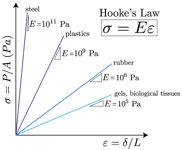
In order to model the mechanical behavior of materials, you can use Hooke’s Law. Hook’s Lab shows the linear, elastic relationship between stress and strain.
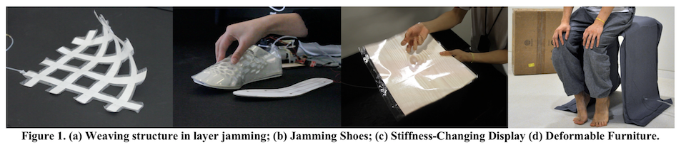
Alternative Idea: Introducing the jamSheets design to my Neumatic Gripper to Create a Hybrid Gripper
To modify the design from the Pneumatic Actuators, I will be adding a second chamber to my previous design that will introduce a vacumm chamber to stiffen the gripper once bent and strengthen the gripper to hold heavier loads. This second chamber will be inspired by jamSheets, a project done by people in the Tangible Media group in the MIT Media lab. This works introduces layer jamming as an enabling technology for designing deformable, stiffness-tunable, thin sheet interfaces. Interfaces that exhibit tunable stiffness properties can yield dynamic haptic feedback and shape deformation capabilities. In comparison to the particle jamming, layer jamming allows for constructing thin and lightweight form factors of an interface. We propose five layer structure designs and an approach which composites multiple materials to control the deformability of the interfaces. We also present methods to embed different types of sensing and pneumatic actuation layers on the layer-jamming unit. Through three application prototypes we demonstrate the benefits of using layer jamming in interface design. Finally, we provide a survey of materials that have proven successful for layer jamming.
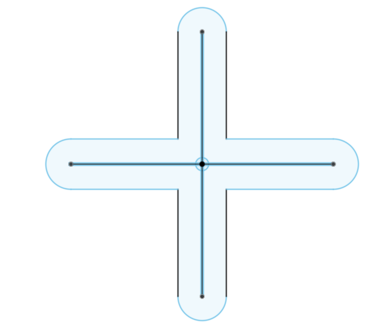
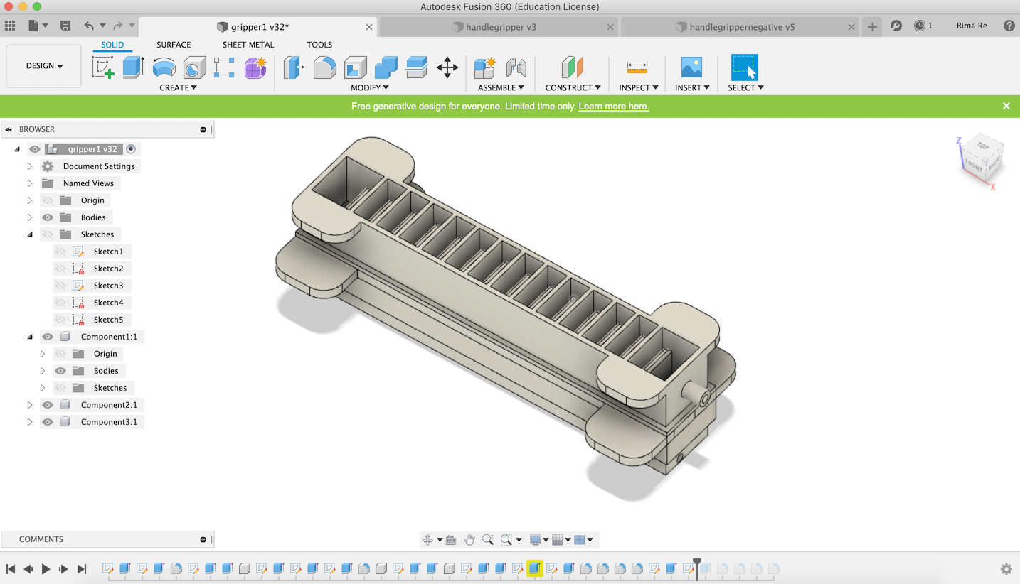
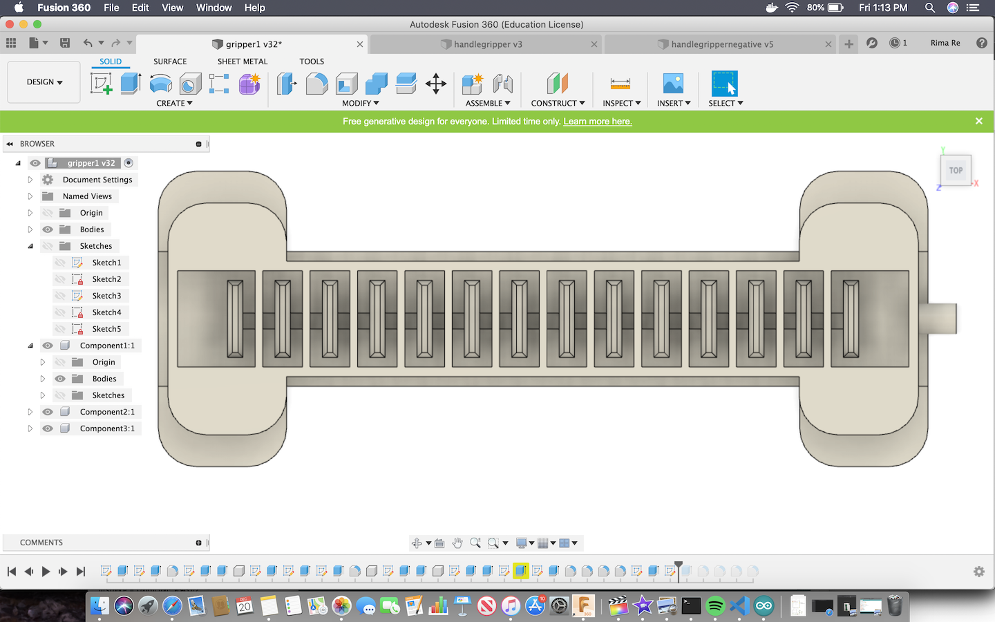
Making the Molds in Fusion 360
My first design for a four handle gripper was going to be different from the gripper that I did the week before. I realized how hard it was to cast silicone and wanted to make one mold for time suffeciency. However, there were many design flaws for this example. It would basically only be able to grip circular objects or really small objects. Because the only thing actuating the grippers is air, soft robotics is super difficult to make precise motions. Therefore, if there was only one air chamber, it would be very hard to control the motion of the gripper. That is why I eventually decided to create 4 grippers, similar to those that I made last week, that would work together to grip objects.
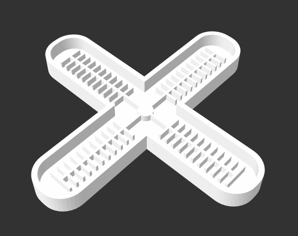
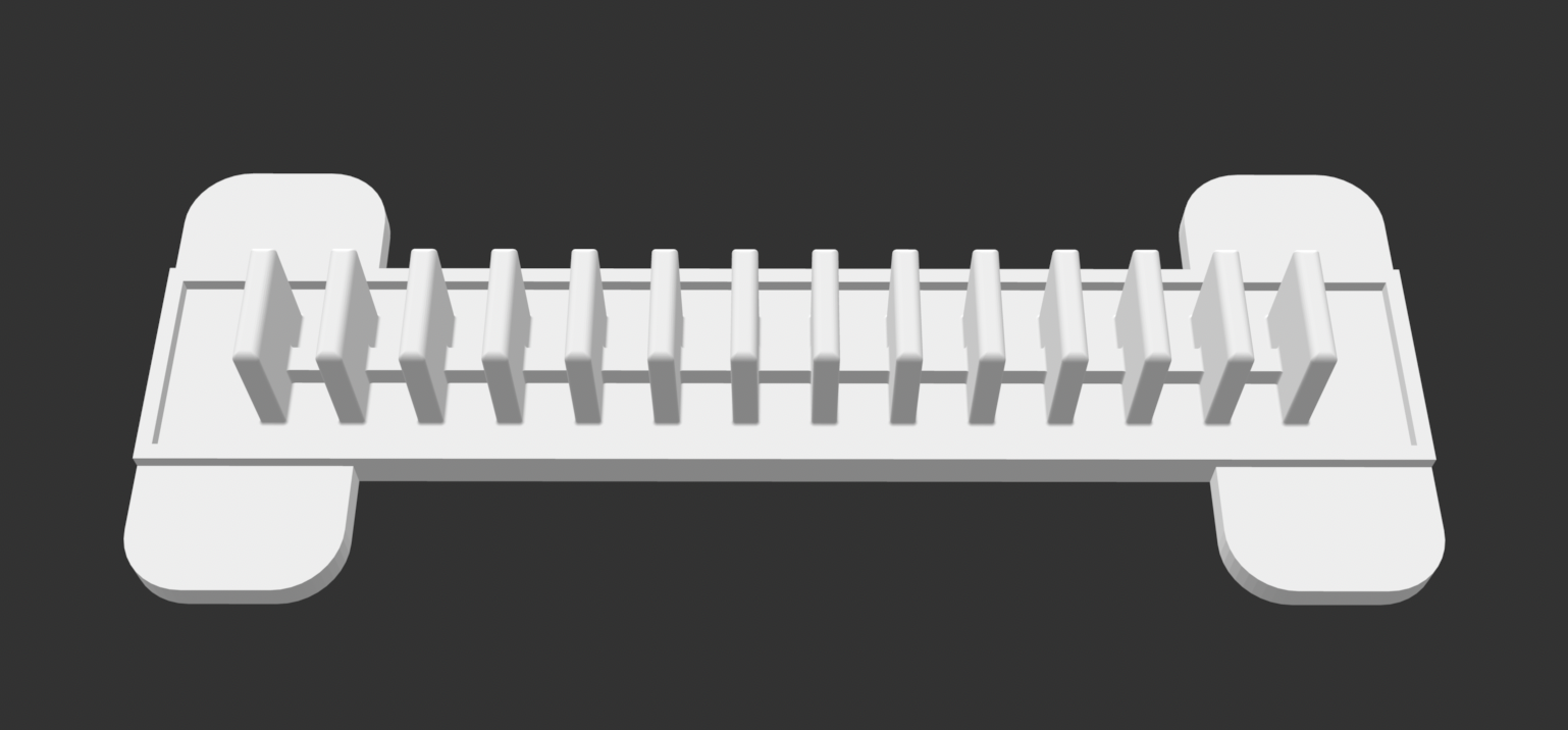
These are my designs for the final grippers. More information on how the grippers work can be found here. I took a lot of inspiration from the PneuNets design from Harvard but modified the base of one of the molds.
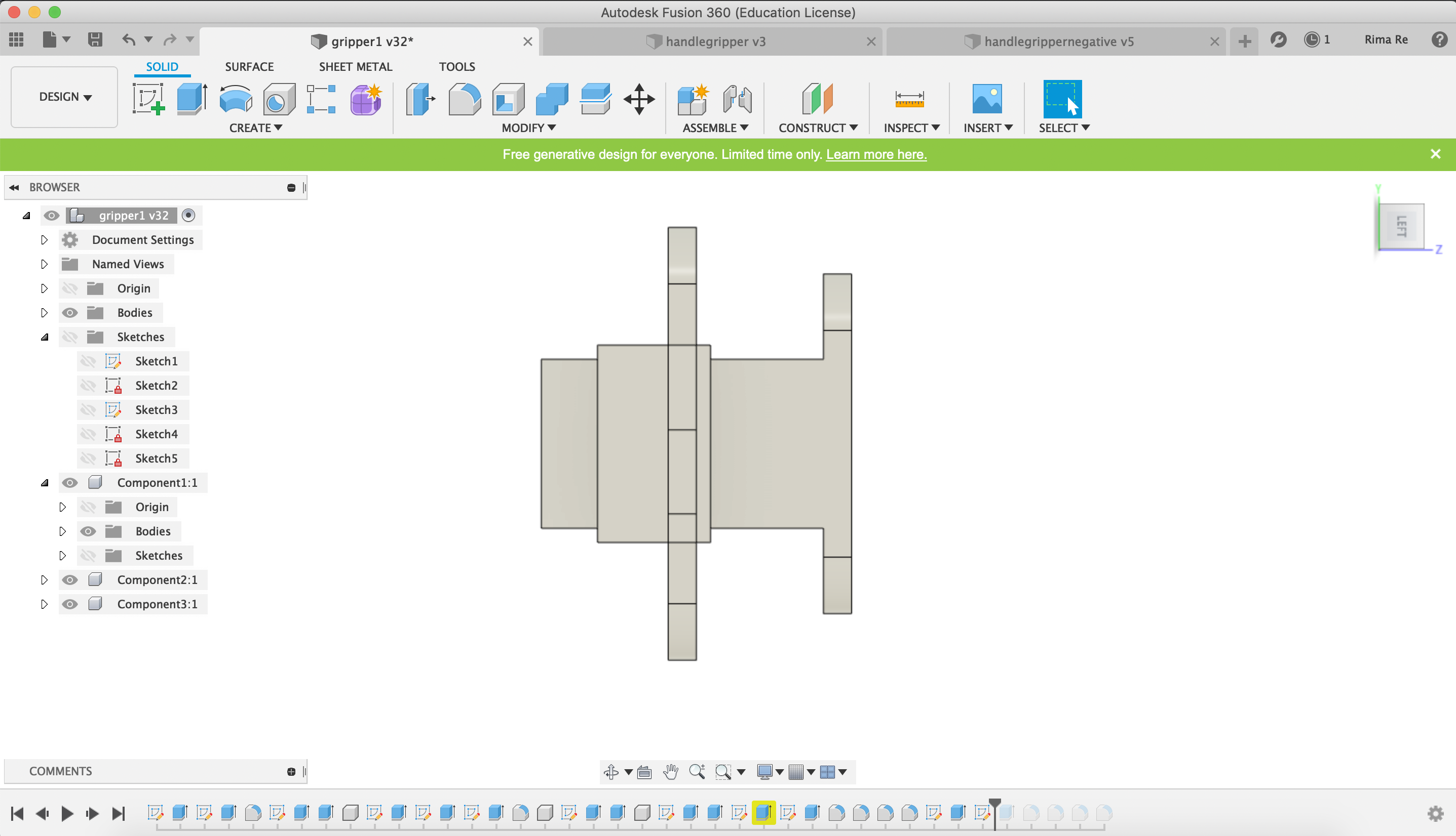
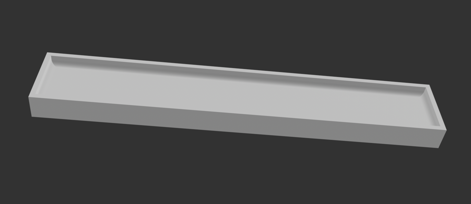
This vaccumm mold, unlike the others was created first positivley and then I subtracted it from a block to get the negative mold that I could use.
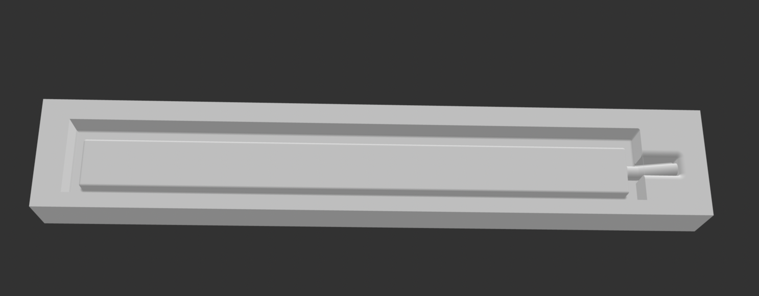
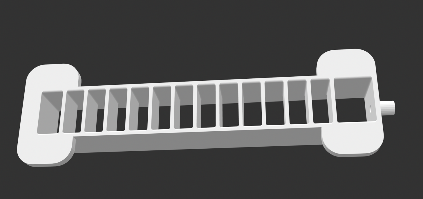
This was the mold that I majorly changed the design for. In the orignial Pneunets design, there are grooves on the base so instead of the top mold being glued to the botton (which is what I did), they would be placed ontop of eachother and more silicone would be poured inbetween the molds to attach them together, and the grooves would be where the silicone would flow. However, because I wanted to glue my molds together because I found that to be much more realiable, I got rid of the grooves. The original Pneunets design can also be found in my soft robotics week page.
3D Printing Molds
To make my molds, I used the Sindoh 3D Wox printer. However, the first time I printed I didn't change any of the settings on the printer. When I got my molds however, a huge problem during the casting process was the air bubbles caused by my first mold. Because the infill of the 3D printed model was around 30%, there were alot of air pockets in my mold. Therefore, when I poured silicone into my models, and put them into the vaccumm to get rid of the air bubbles in the silicone mixture, the molds that I first printed were interoducing more airbubbles that were in the molds into the silicone and overall increasing the number of bubbles in my mold. This made it virtually impossible to get rid of bubbles in my smaller molds where a single bubble could make the entire gripper burst. I tried to see if instead of 3D printed my mold I could use the CNC machine to machine the molds, however the detail for all my molds were so small it would have been impossible. Therefore, I just printed a second print of all my molds where I set the infill to 100% and changed the layout of the print to "grid" to really limit the amount of airpockes in my molds.
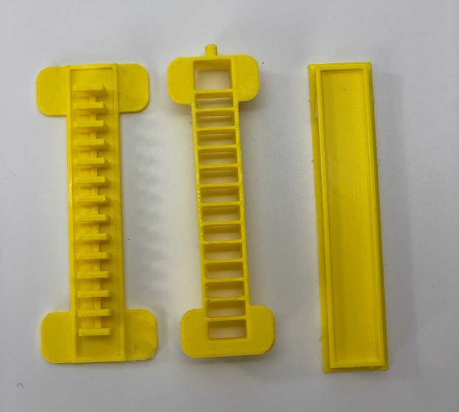
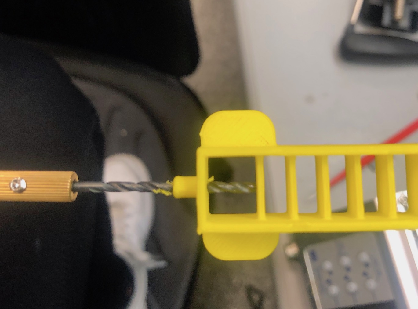
Because depending on the orientatation of your print, 3D printers have a hard time creating perfect circles with the correct diameter. I just hand drilled to make the hole the correct diameter. A rod will be inserted in this hole to make room for the straw to be interted after the mold sets.
Casting and Glueing Silicone Process
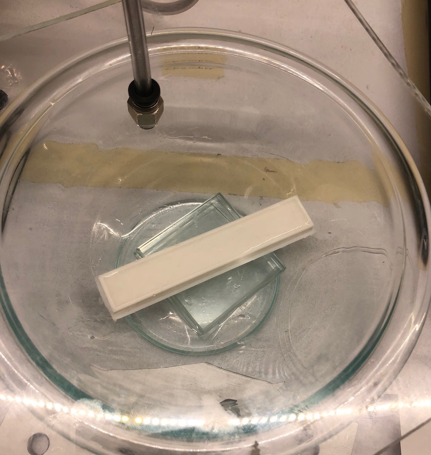
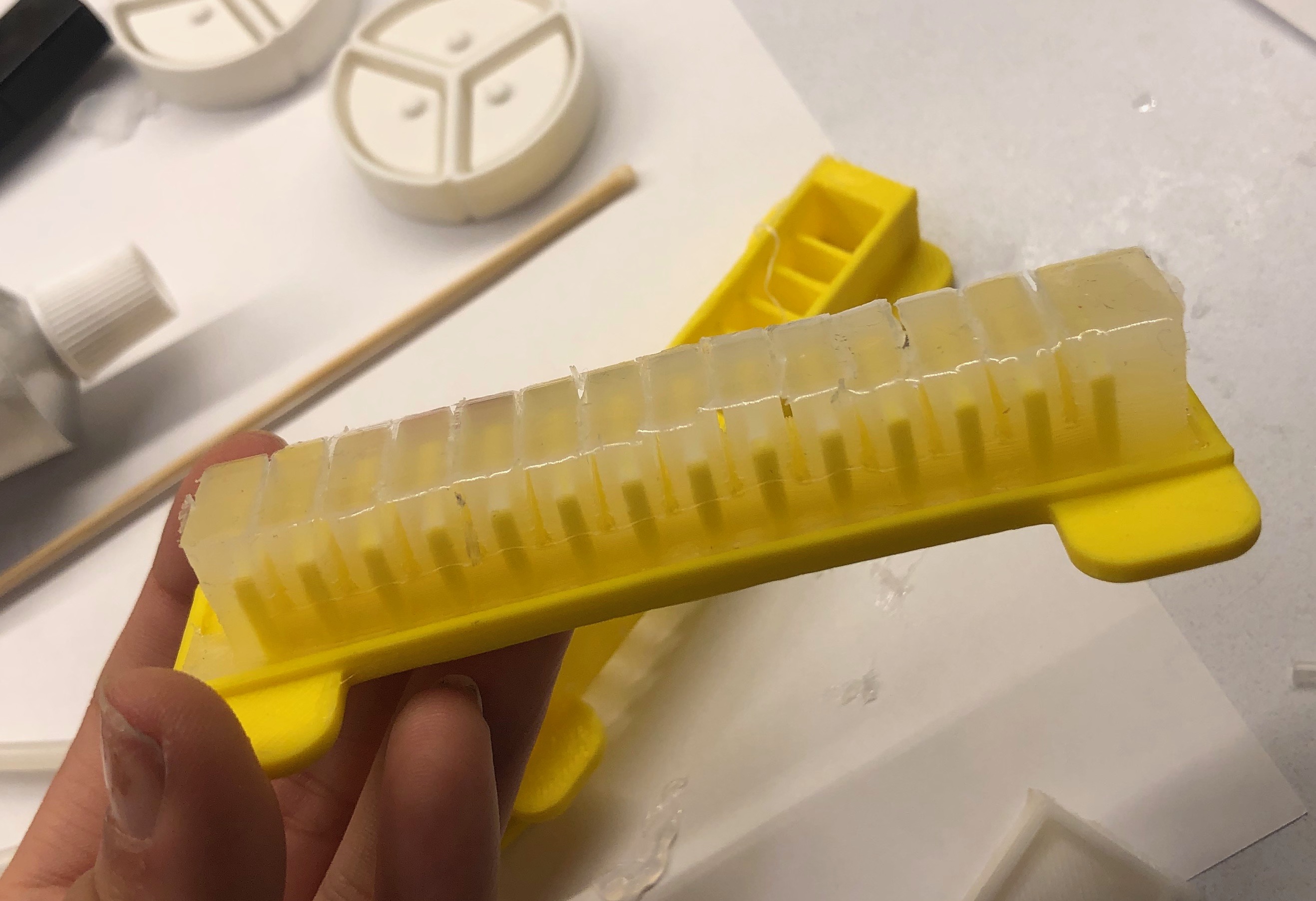
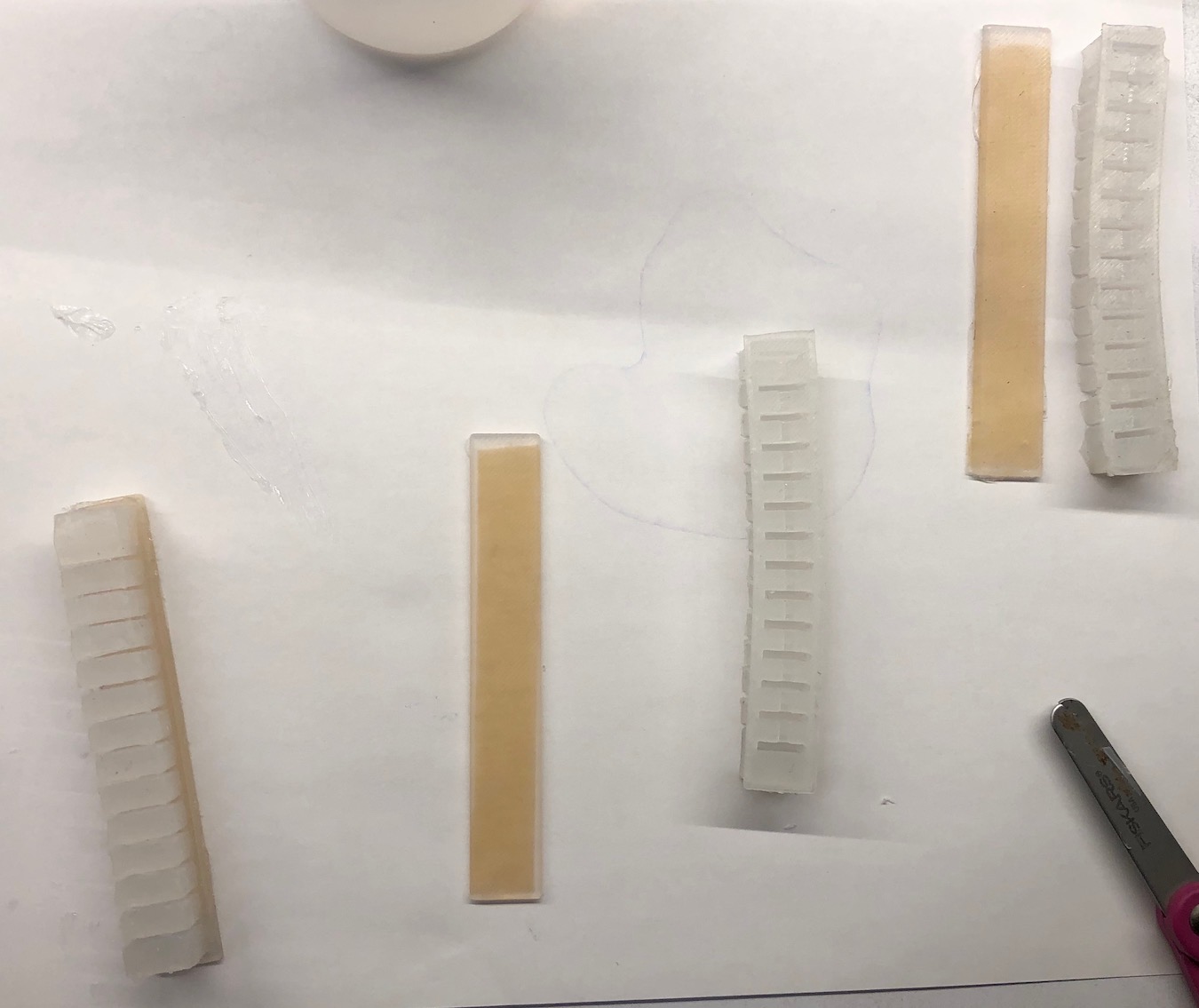
A fuller descriptiong of the casing process can also be found in my soft robotics week. A difference of last week, is after I poured the silicone in my molds, I also put the mold with the silicone to try to get rid of all of the bubbles that were also created after pouring the silicone into the mold.
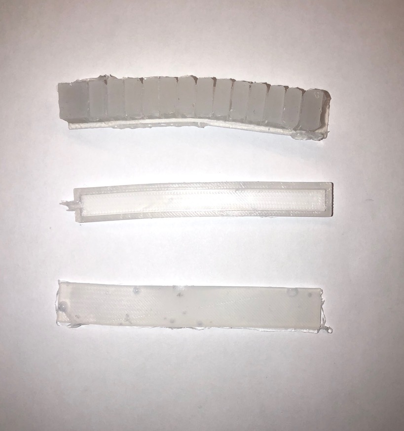
However, like I said with the first molds that I printed this just caused more bubbles that I could not get rid of. Once I printed the second mold this created much better casted parts. This is the difference between the first and second mold.
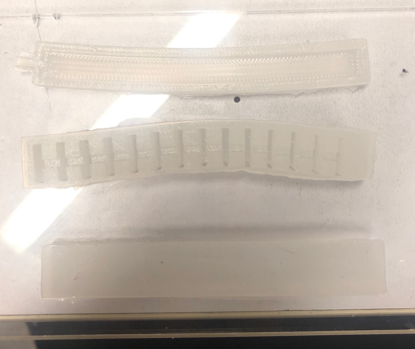
To take off the parts, I took off the hot glue, glueing two of the molds together. This is how the cured molds look in the molds.
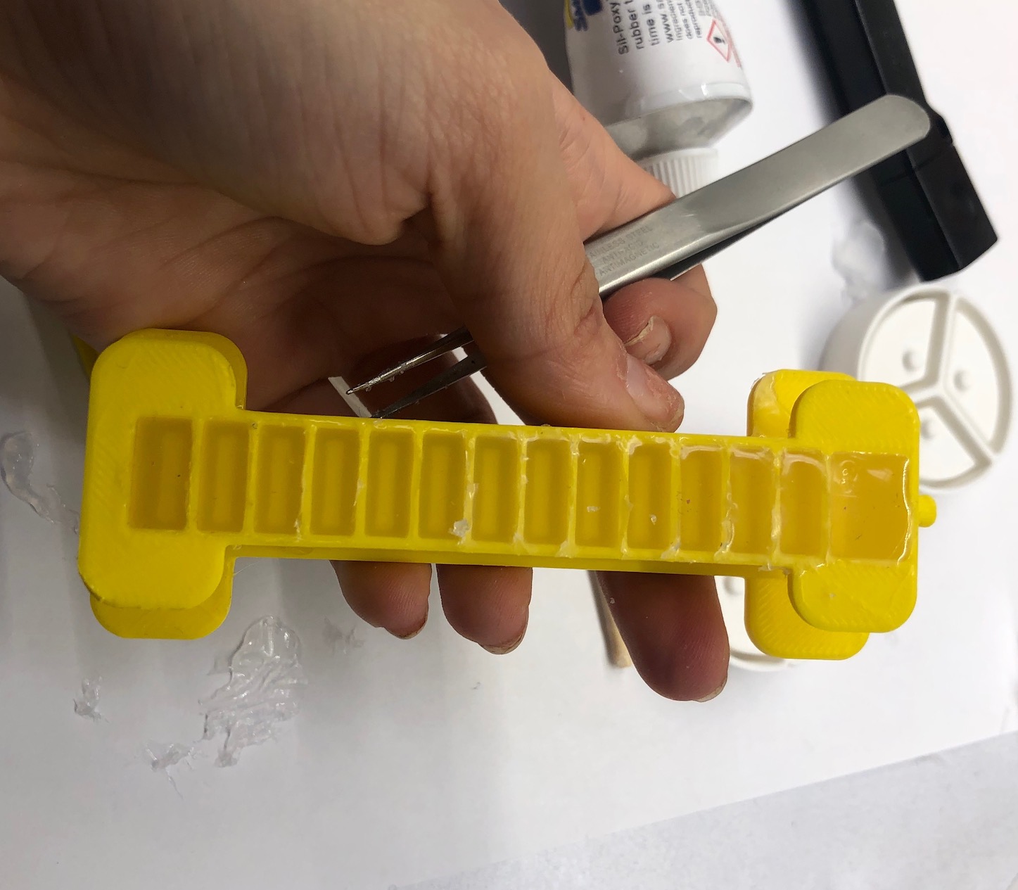
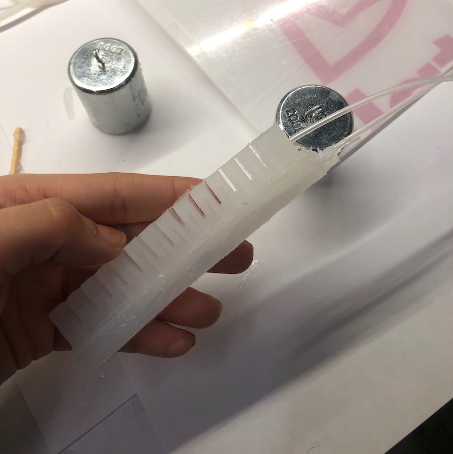
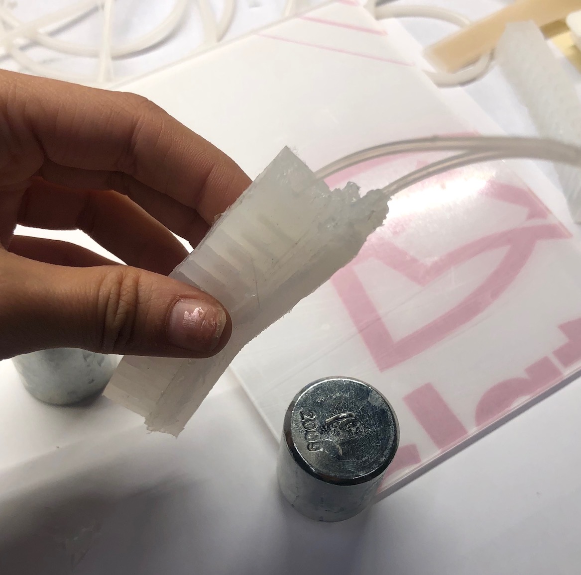
Not many things stick to silicone to I used Sil Poxy, a good siliocone glue. The glueing process I also found to be a difficult process. This is because if there is any hole in the glueing process, this lets air escape and the gripper will not work. The first few times that I glued my parts, there were multiple holes when I finally tested my parts. To get the best results, you need to make sure the glue is perfectly level on a thin layer on the bottom casted part. Then, you need to make sure you put the top casted part in a way that none of the edges hand off the edge of the bottom mold. Once that is done, add a ayriclic sheet over both glued parts and place weights on top to make sure that the parts are glued together. The drying process takes about 12 minutes and then you can check for leaks and add more glue where needed.
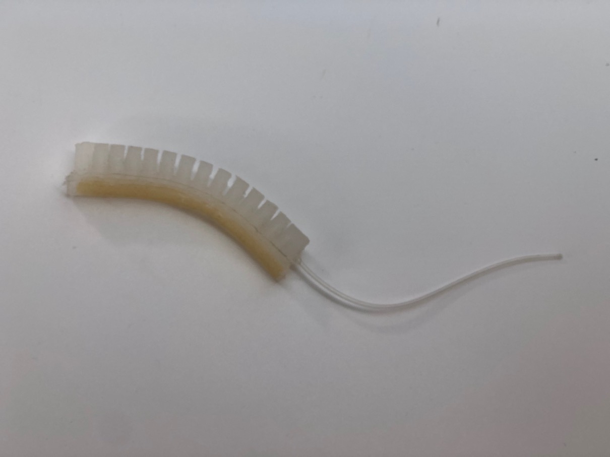
Another mistake I made the first time was not glueing the tubing properly to the gripper. Where the tube comes in is a likely hole for air to come in and out of. I used to just stick the tube in and then put the glue around the opening after the tube was intserted. Instead, what should be done is glue should be placed on the tube untill about 1 mm from the opening. Then, insert the straw slowly, turning one direction as you are inserting the straw.
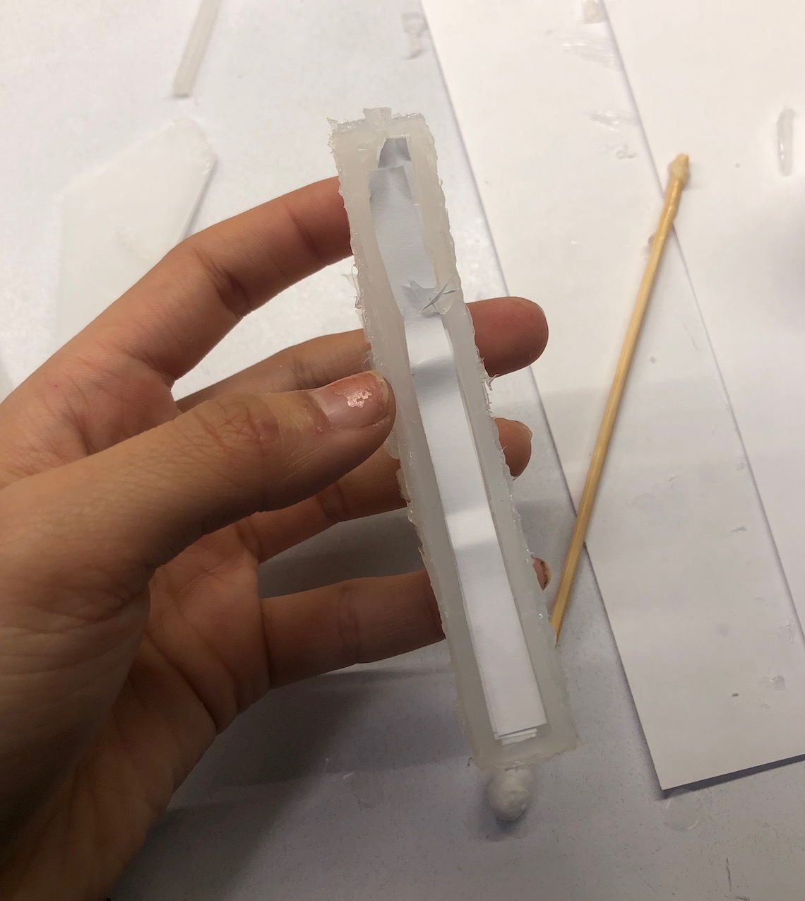
This was also an example of a hybrid gripper that I created with the vaccuum chamber. I wanted to create a design where pumps would actuate the movement of the grippers and then the vacuumm chamber would keep whichever the position of the gripper was so it would be possible to carry heavier objects with the gripper. However, because this is realativly all in research, I decided I would need alot more time to perfect this design in terms of designing the correct dimensions for the vacuum chamber and material for the paper in it that I decided to abandon the two chamber idea for another time.
Handle Design and Manufacturing
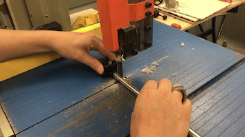
Modifying Selfie Stick
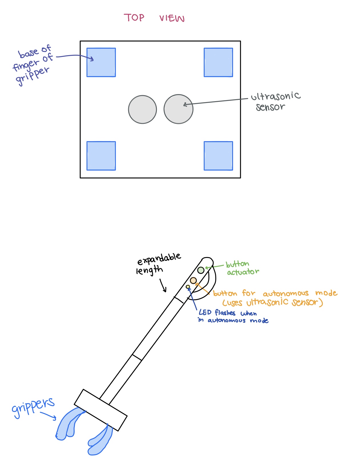
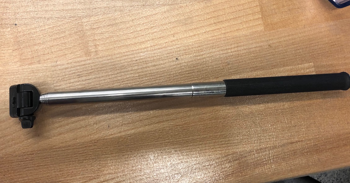
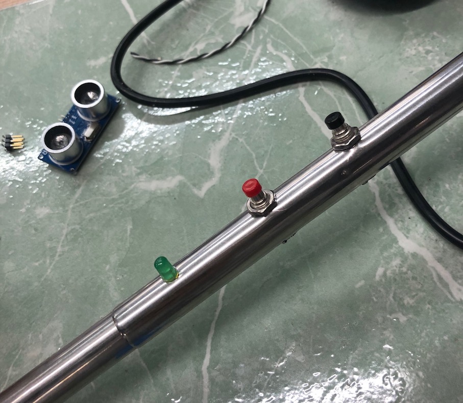
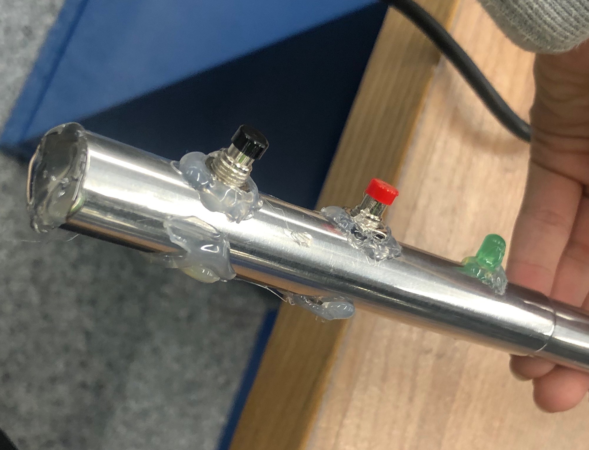
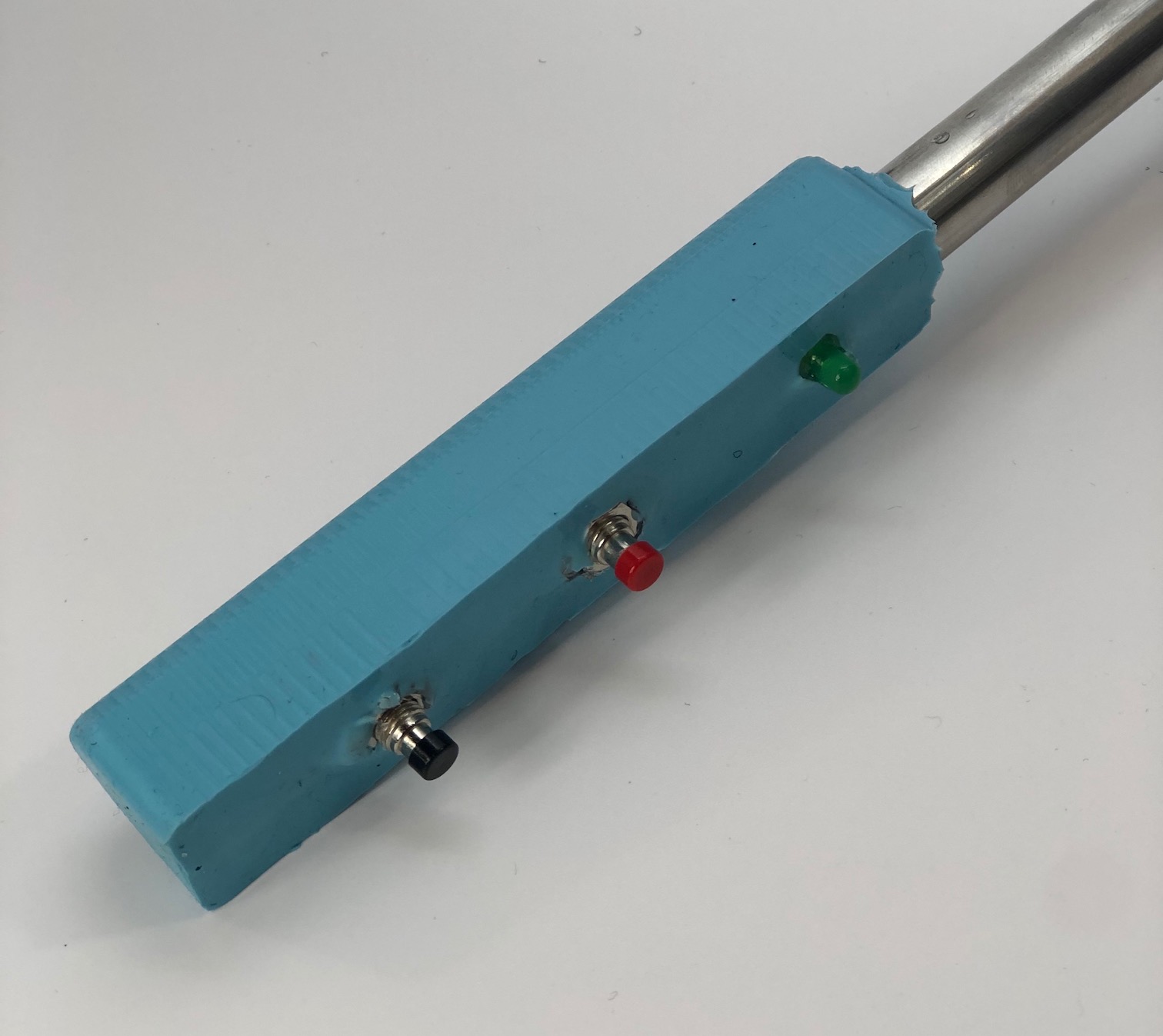
The main mechanical rod of my Pnematic gripper started off as a selfie stick. Because I wanted to make my gripper look as packaged as I could, I wanted to find a way for all of the wiring to be on the inside of the handles. The first thing that I did was check which parts of the selfie stick were hollow so I would be able to run wire through. I found that the bottom was hollow and just cut the bottom off the selfie stick. I also got rid of the handle of the stick because I wanted to make another handle that would incorporate the buttons and LEDs.
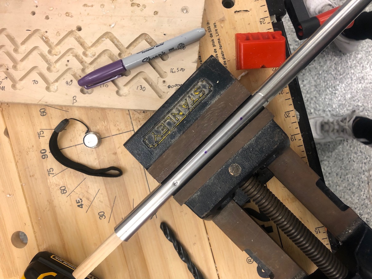
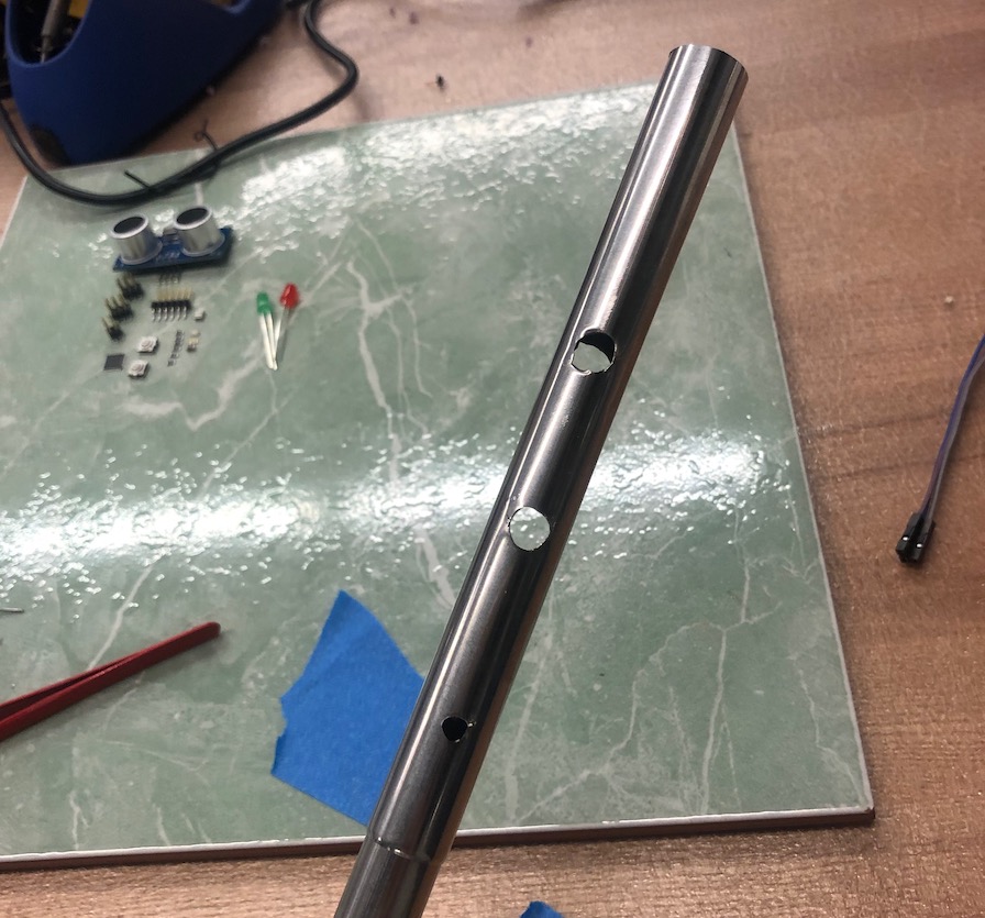
The next thing that I needed to do was drill the holes for the 2 buttons and the LED. Because the buttons that I was using were fairly large and the length of them were about the diameter of the large part of the stick. Because of this, I just drilled a smaller holw for the LED and for the two buttons, I cut two through whols so I could insert the buttons vertically from one side of the stick and insert the buttons that way.
Attaching Buttons and LED
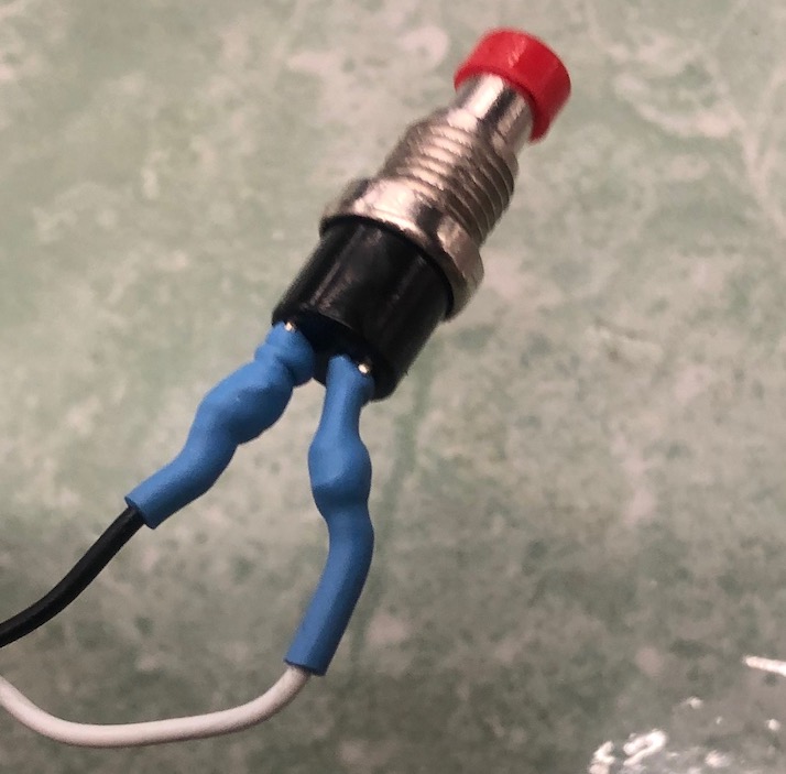
Because the selfie stick is made out of metal, it made is dangerous for shorts if there were any exposed wire on the inside of the stick. Because the buttons connections to the wire would be open, I added some heat shrink between the button pins, solder, and wire to make the buttons completly insulated.
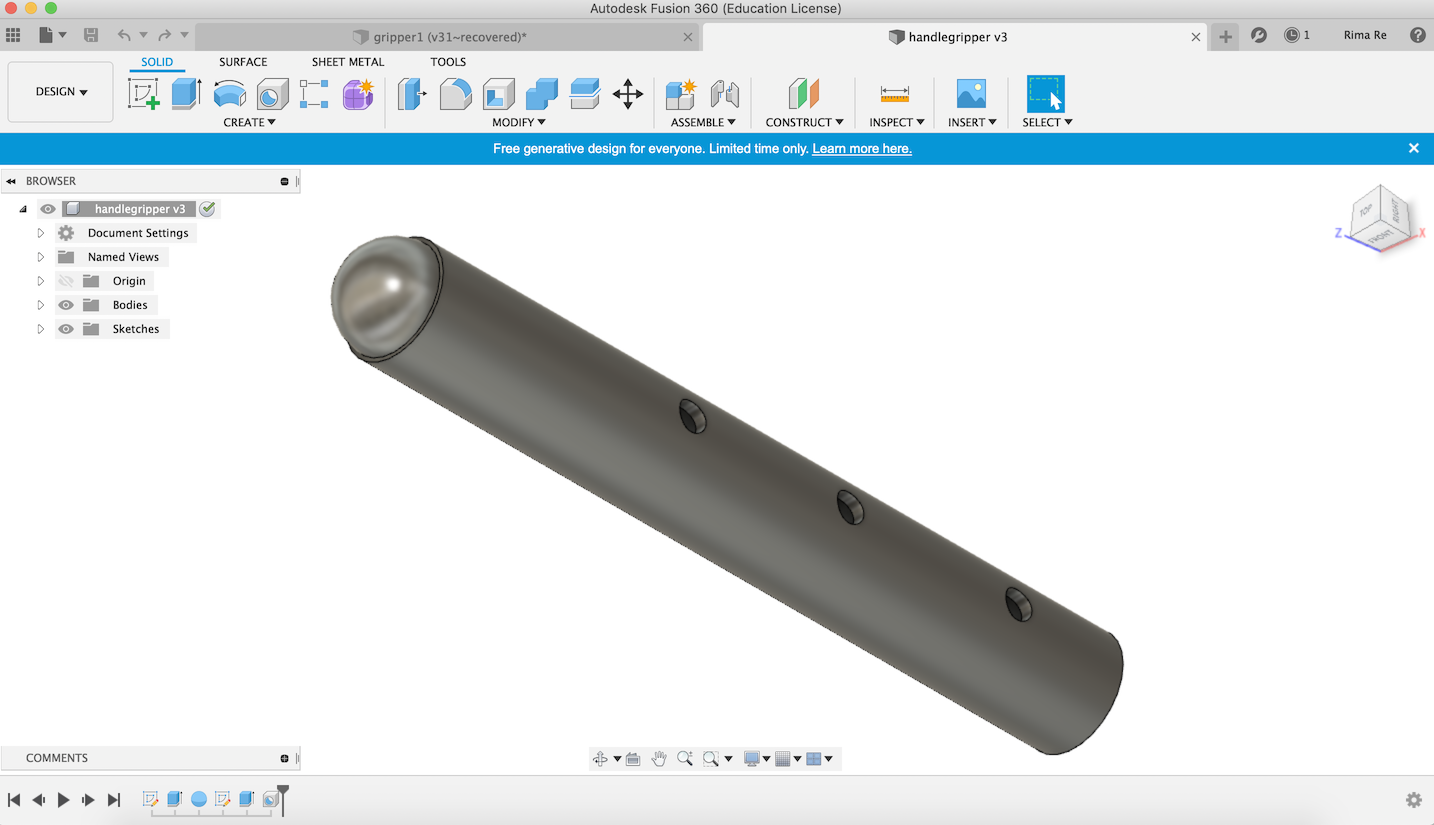
Creating Mold In Fusion 360
The first mold that I created was the positive of the handle that I wanted to create. I was first thinking of making a silicone handle and just slipping it on to my handle of the gripper. However, once I subtracted that mold from a negative block I realized that it wouldn't be machinable because it was hollow.
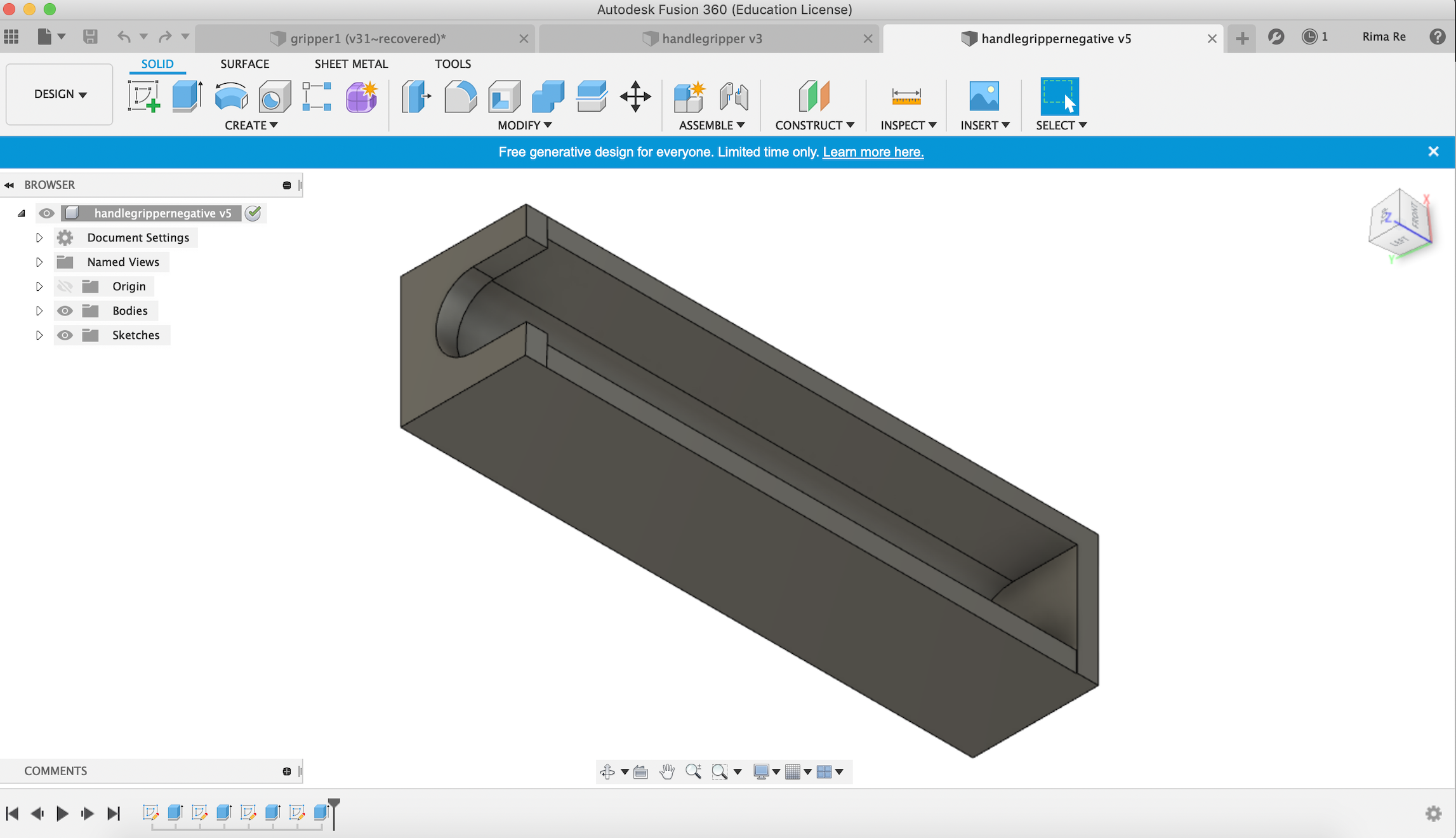
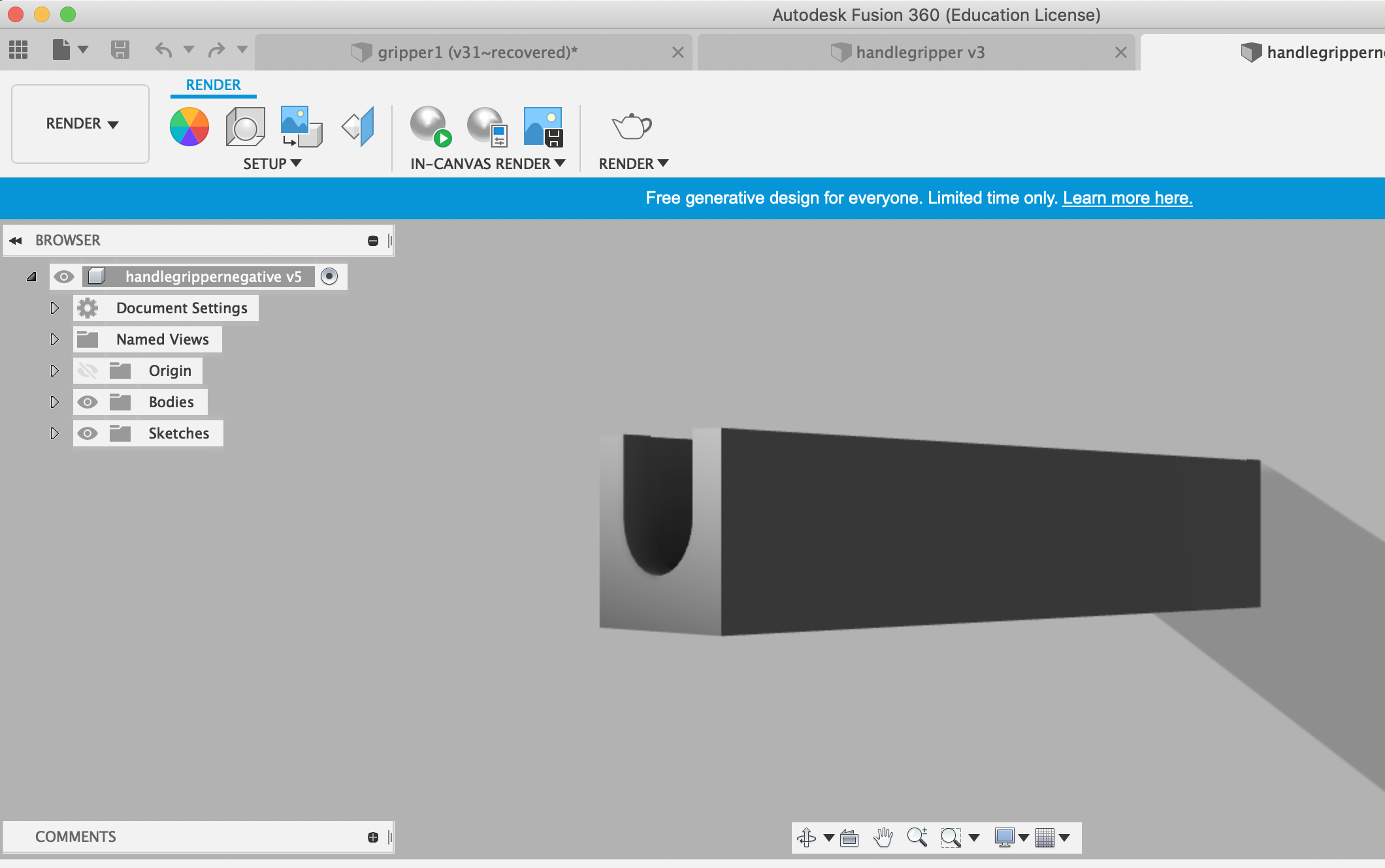
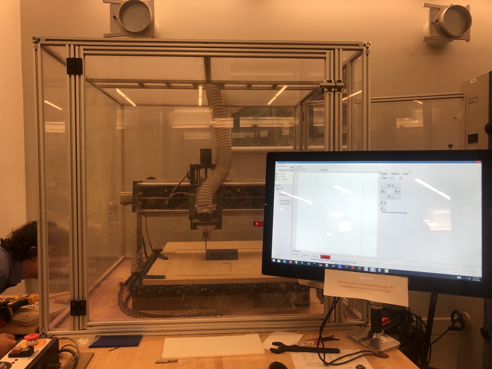
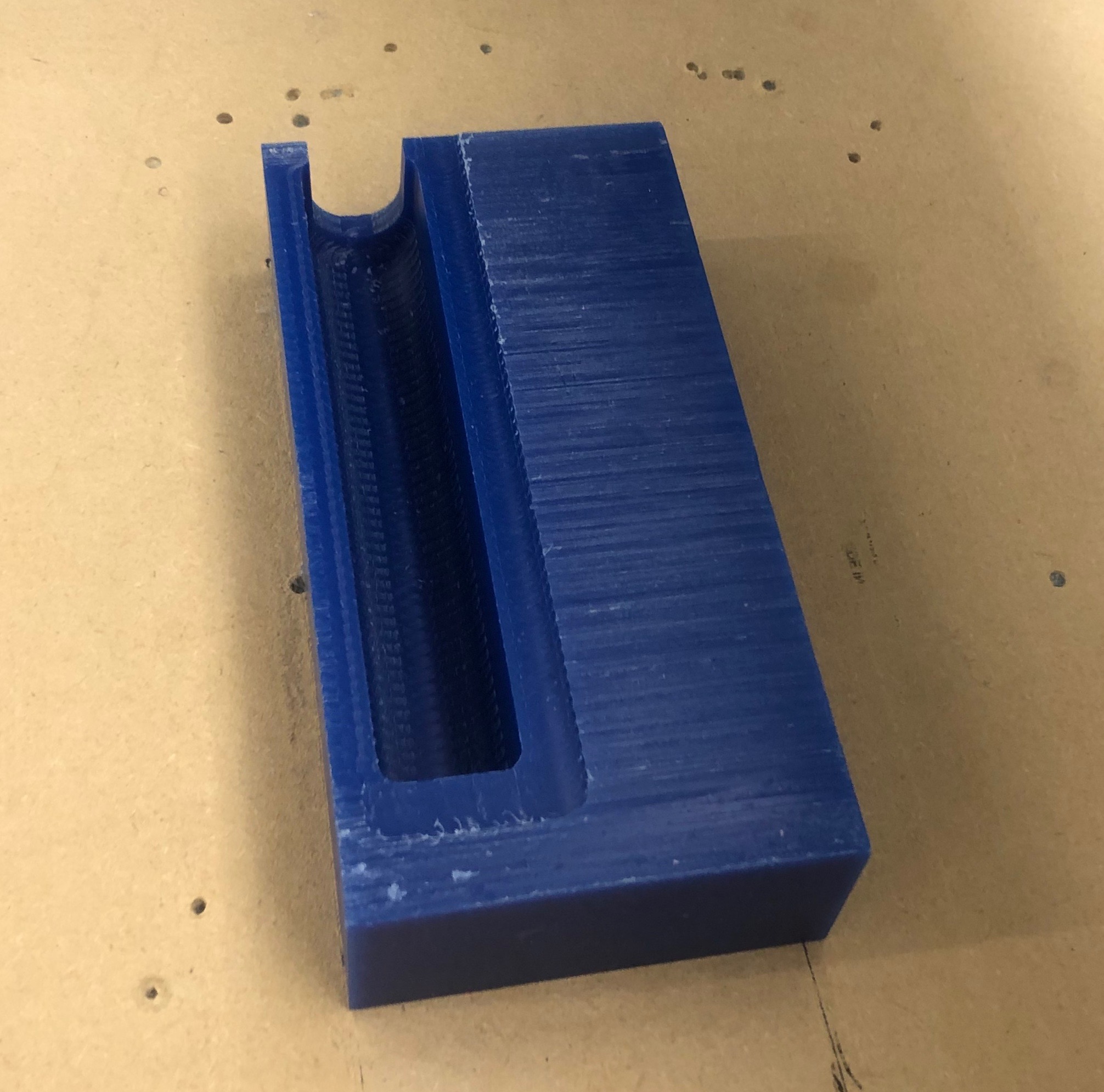
Therefore I decided to machine a holder for my gripper that I would be able to place in this mold and just pour OOMOO directly ontop of my gripper. Usually this material is used to create the molds but I was using it as my final mold which I thought was unique. After I finished making the positive of my holder, I machined it.
Molding and Casting Gripper
Because I don't want any leaks to get in once I put the stick in the mold I created, before I poured the OOMOO on my gripper, I made sure all of the wholes that I created for the electronics were insulated from the outside.
I also hot glued the bottom and sides of the gripper to make sure no OOMOO could spill out onto the sides aswell.
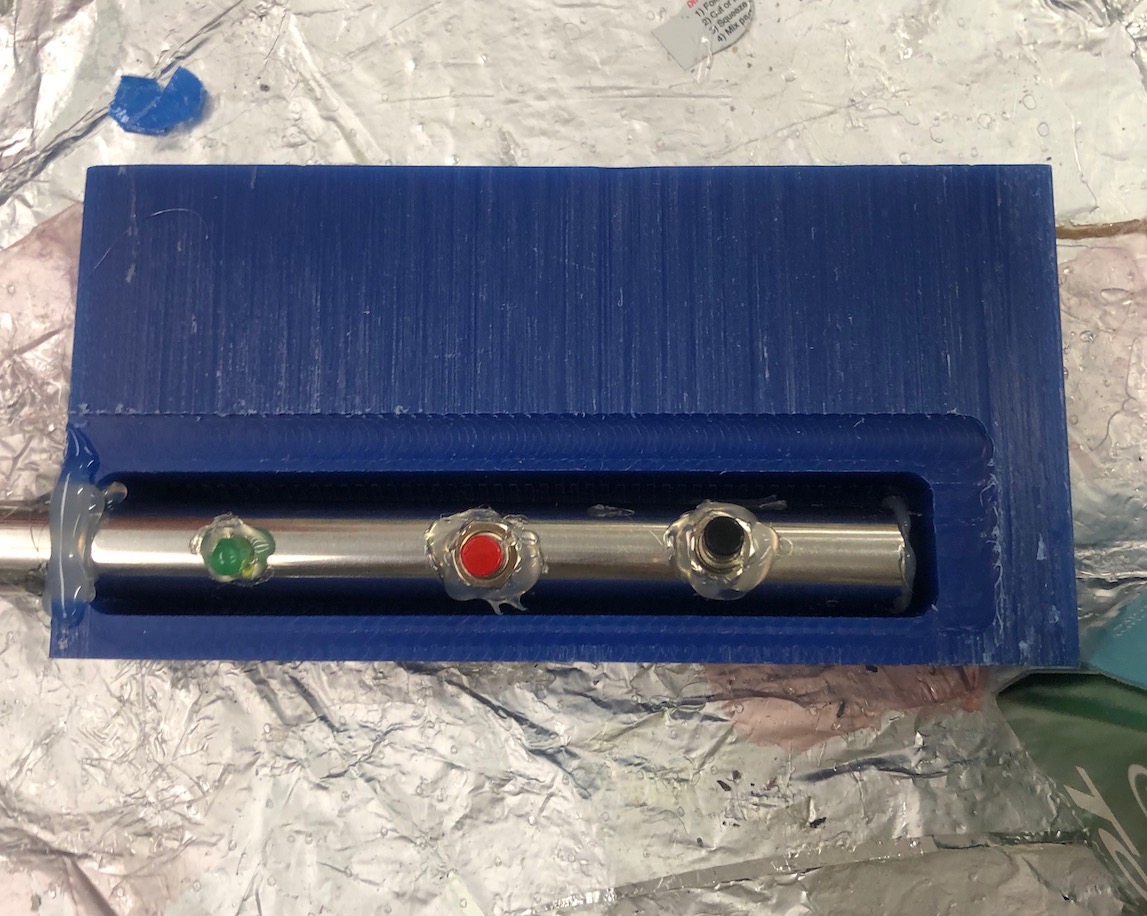
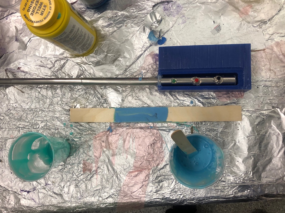
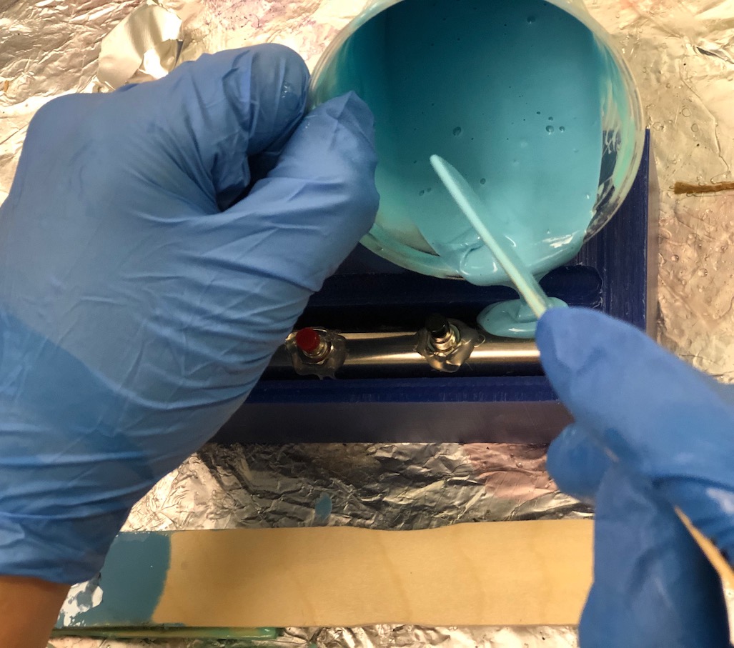
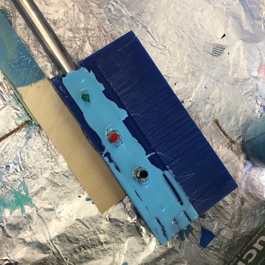
I had to be extremly careful when pouring the OOMOO because I didn't want to risk it getting into the crevices of my buttons to make them unpressible or to cover up my LED.
Electronics Design and Production
CREATING BOARDS IN EAGLE
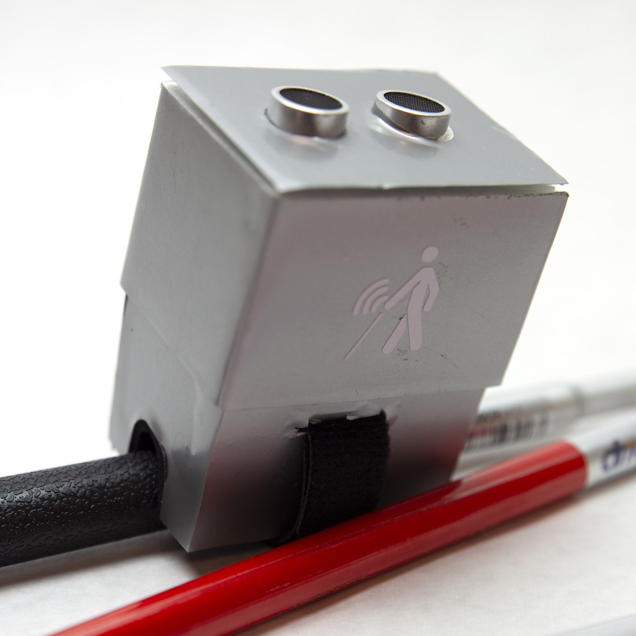
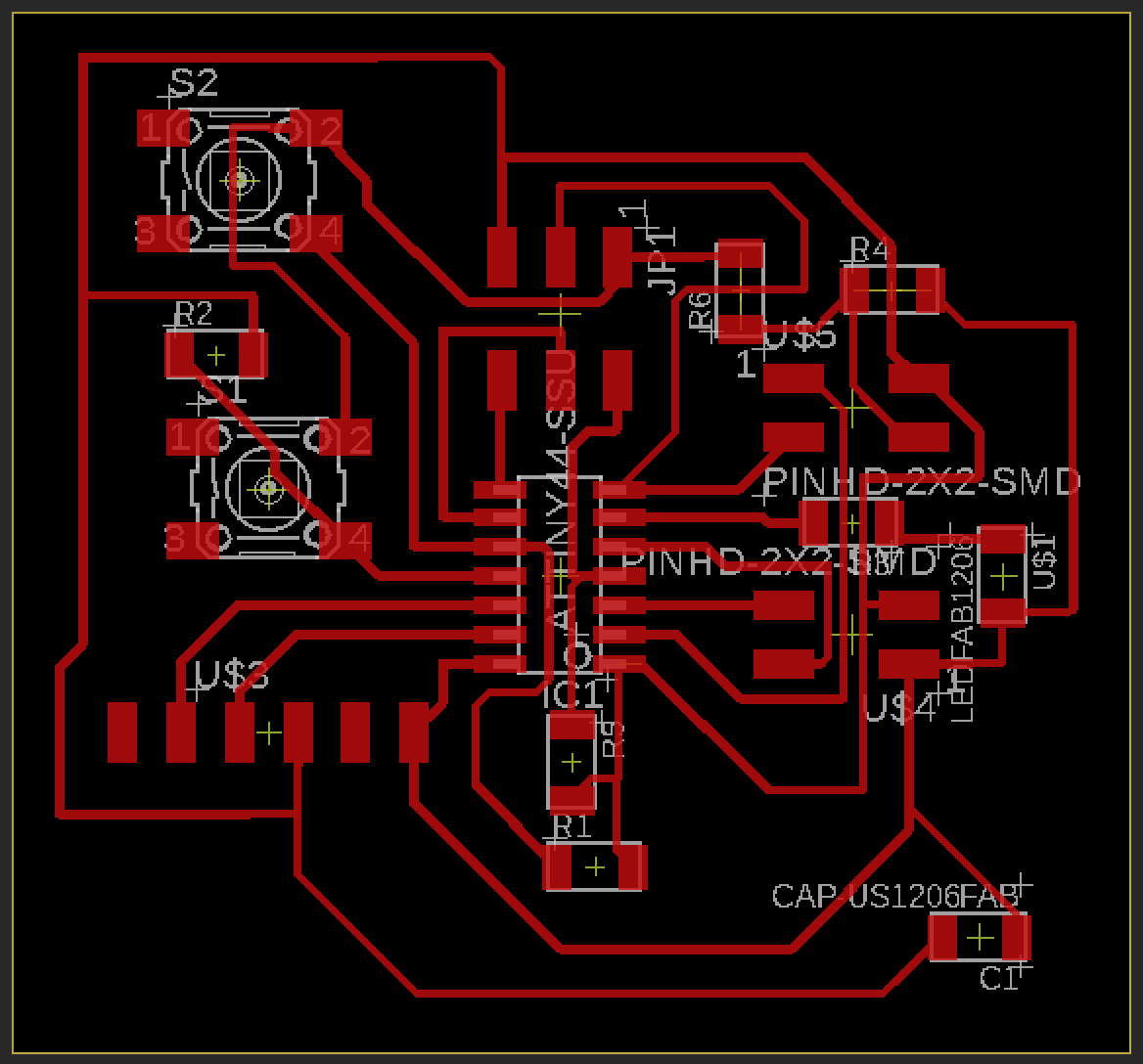
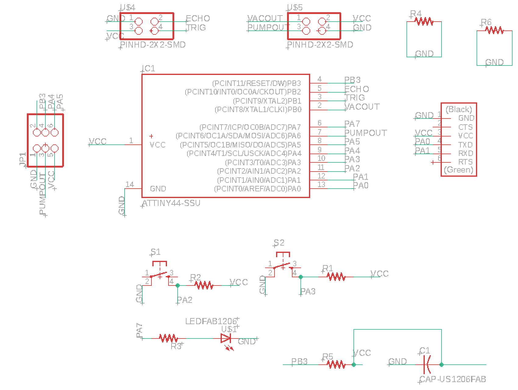
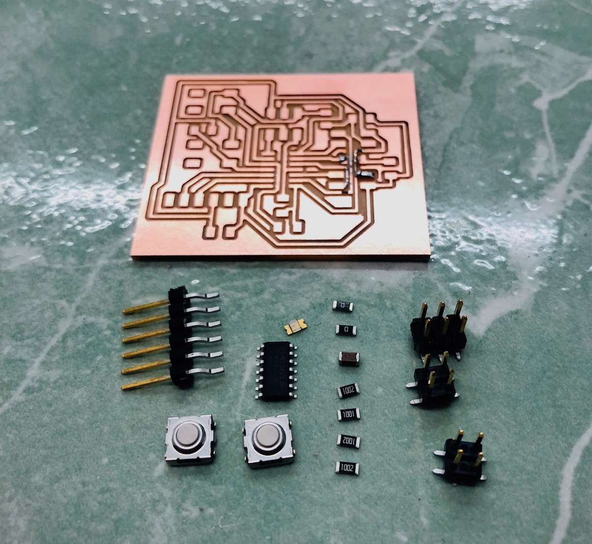
In terms of the electronics for my autonomous pneumatic gripper, I wanted to use two buttons, and LED, and an ultrasonic sensor. The two buttons will be used for manual mode, while the ultrasonic sensor will be used for autonomous mode to know when an object is within grippable distance. I will also be using the LED to help guide the user through autonomous mode. I also need 4 pins to connect with the FlowIO (GRD, VCC, PUMP, and VAC). The pins VAC and PUMP will be letting the flowIO when to turn on the pump and vacuumm depending on what the user does.
Board Using ATTINY44
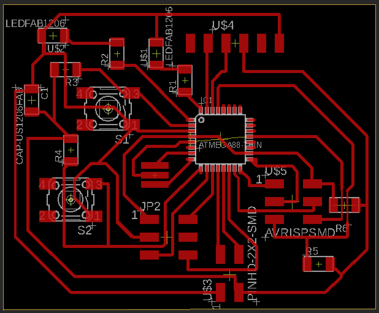
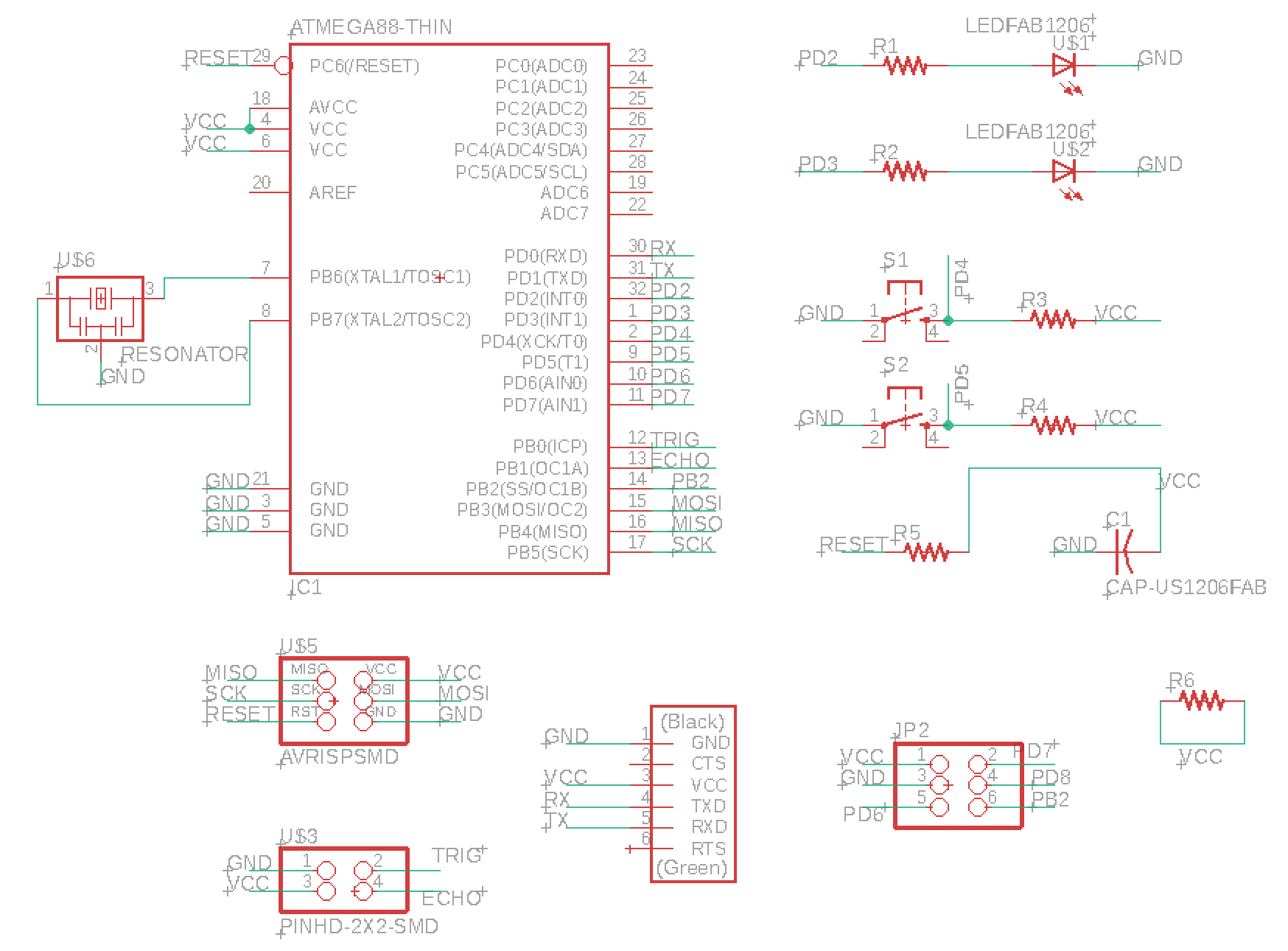
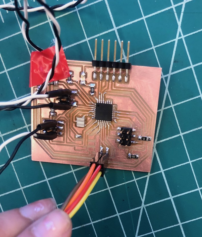
Board Using ATMEGA328p
The Atty44 eventually did not have enough memory to do all of the things I wanted to do in the programming section and it also didn't have enough pins which required me to reuse a programmer pin after I programmed my board. Therefore, I remade the board using an ATMEGA328p mircocontroller.
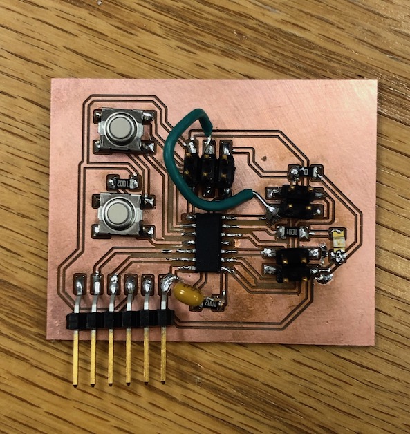
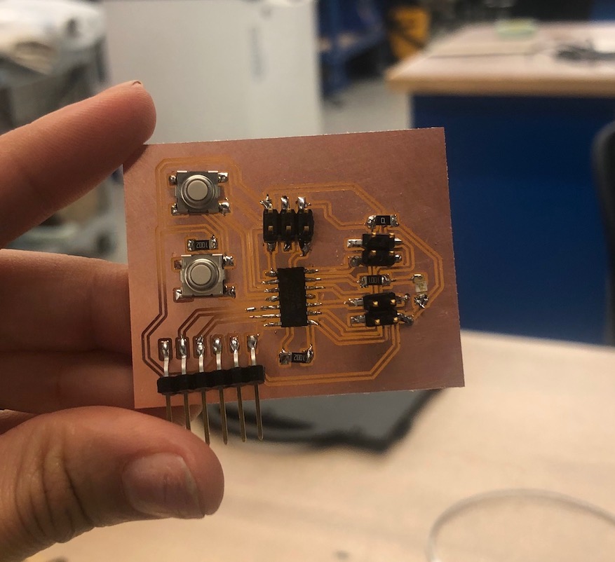
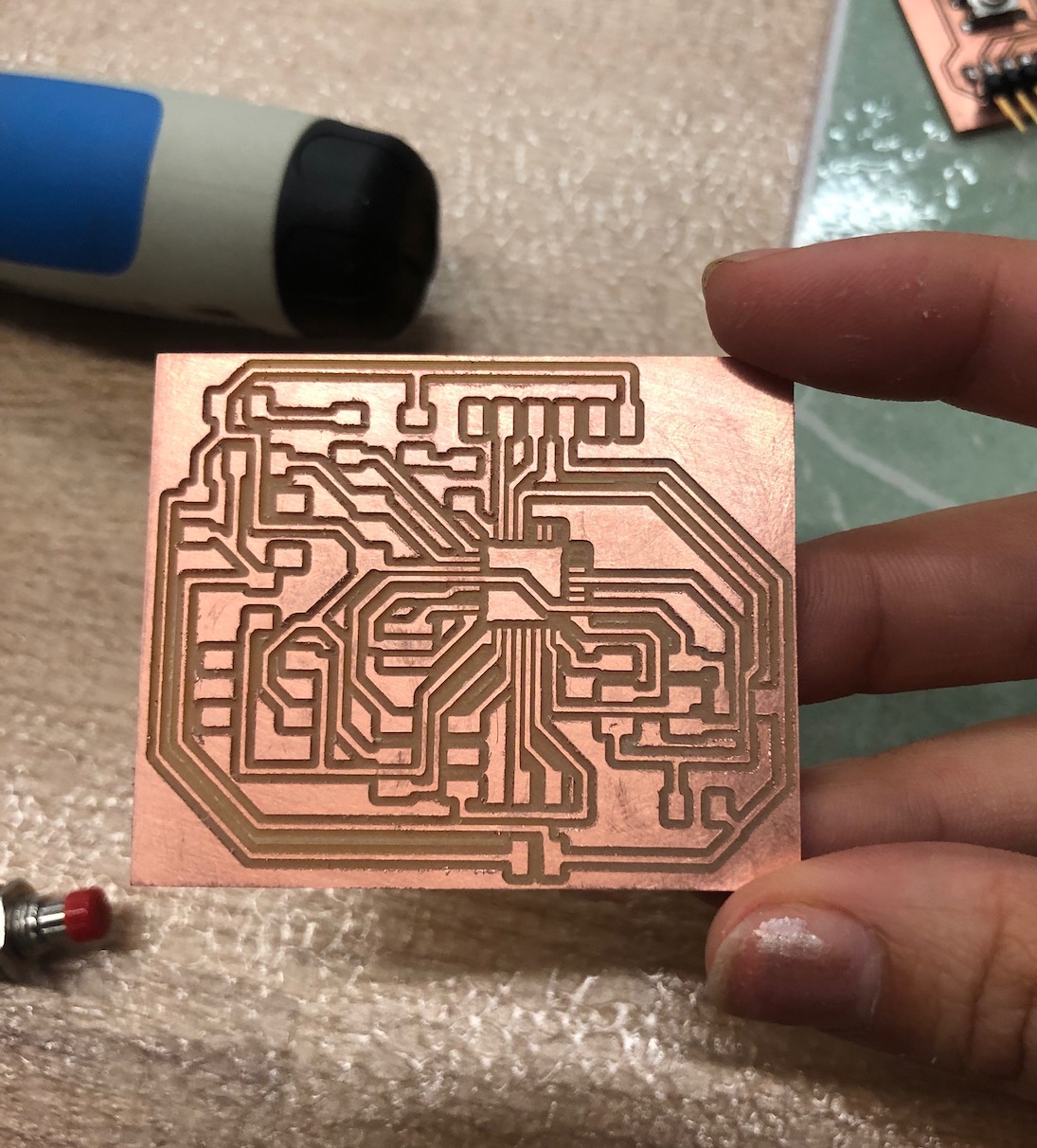
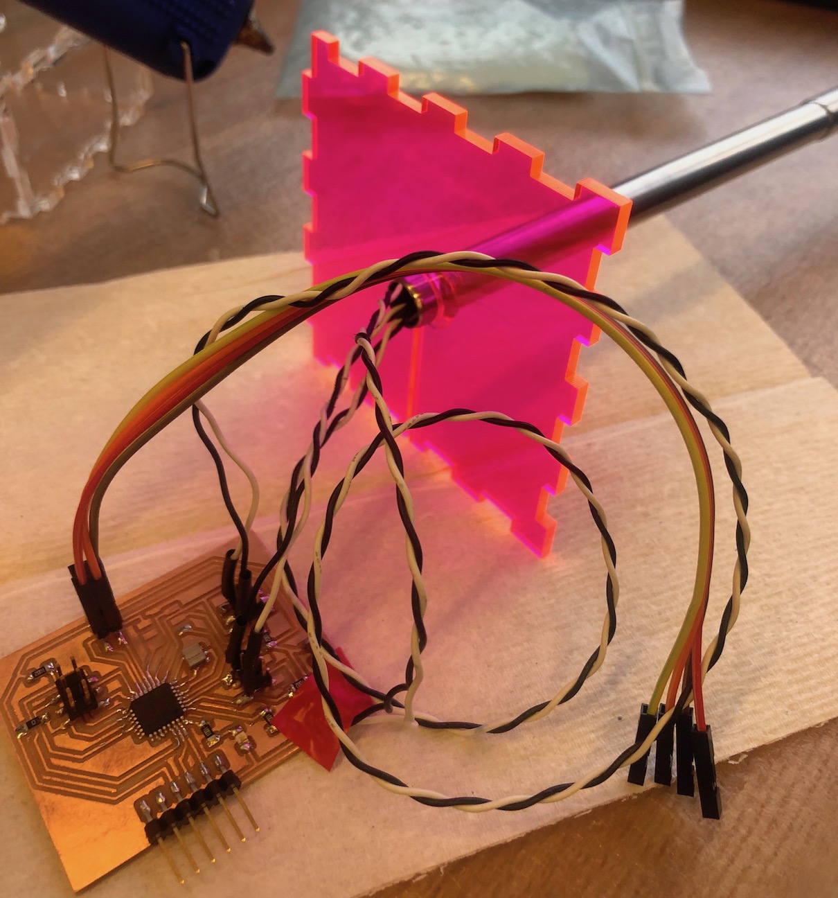
MANUFACTURING BOARD
The first time I designed the board, I actually forgot to connect one of the pins of the programmer to ground and I also forgot to add a capacitor from ground to vcc. Both of these problems caused my board to not work. However, after fixing both problems the board was able to work. So I decided to make a second board with the correct traced and components to make a cleaner board.
However, after programming my board with autonomous mode, the ATTINY44 could not handle all of the things I wanted to do so I remade my board using a better microcontroller.
FInal Board
Programming Board
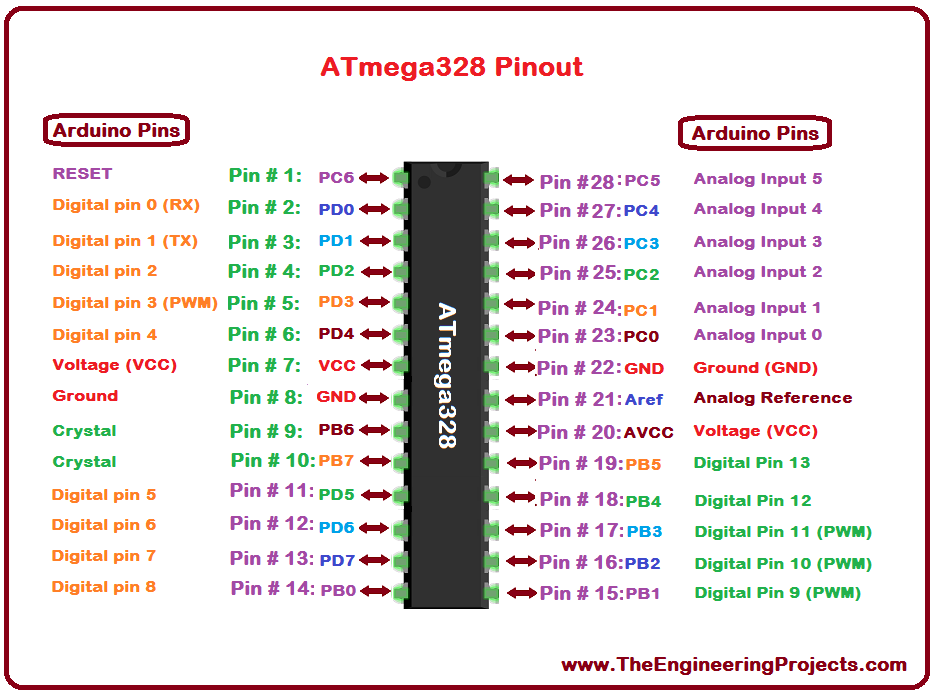
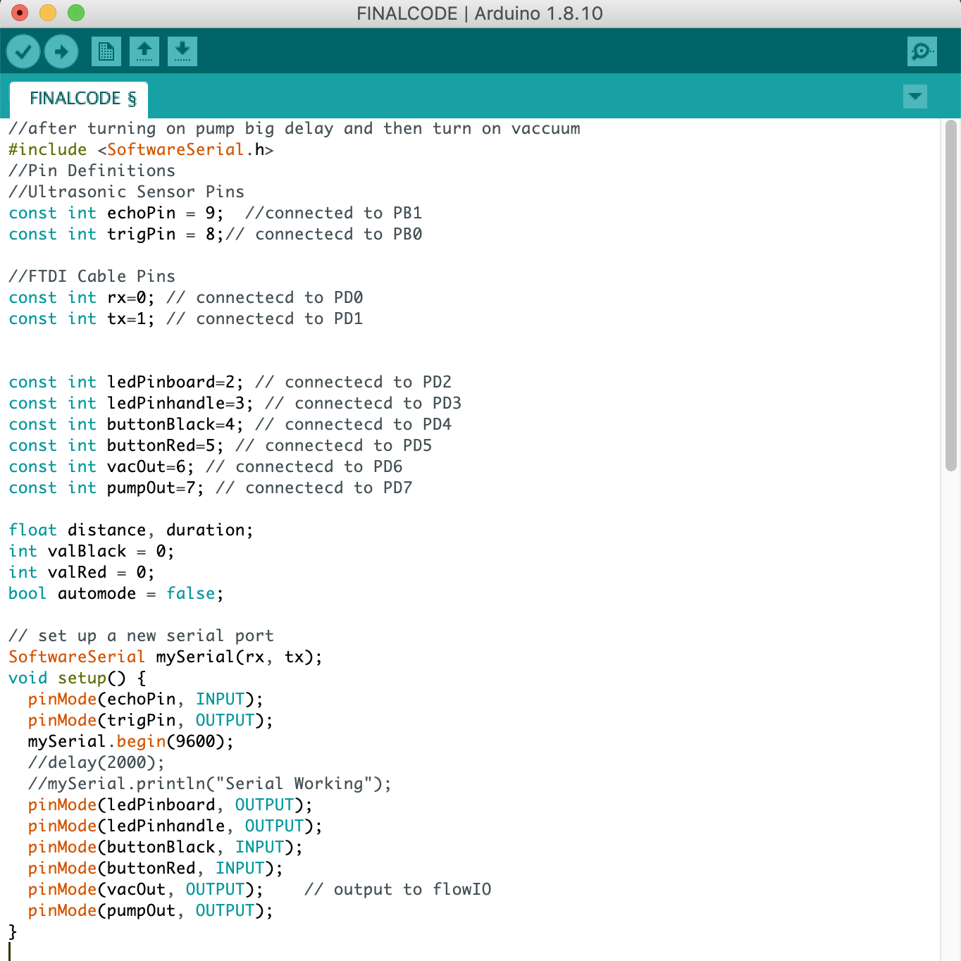
This was the first time I was using the ATMEGA328p. The first thing that I had to do was look at a pinout diagram so I knew what the equivalent arduino pins were that I could put in my code for all my parts.
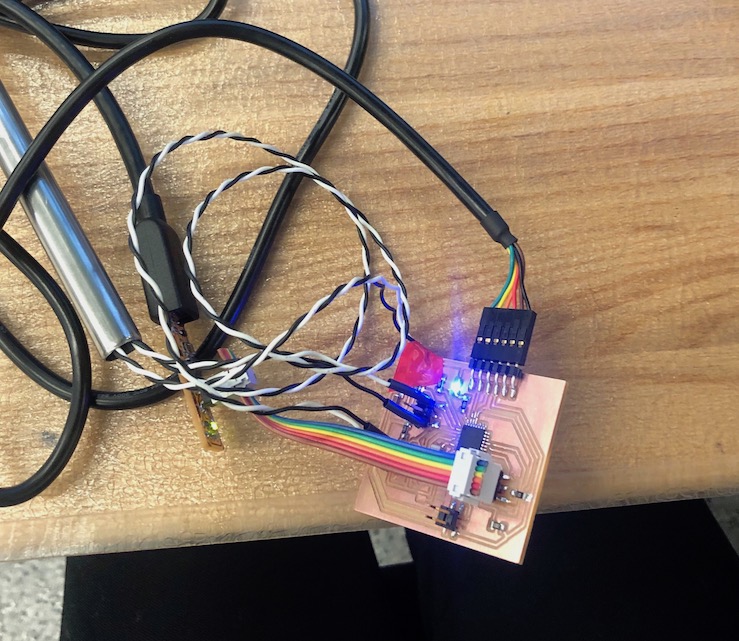
Like I said before, my first two boards eventually were able to be programmed to do simple things like turn on the LED on the handle and the testing LED on the board by the press of a button. However, once I uploaded my ultrasonic sensor code there wasn't enough memory left.
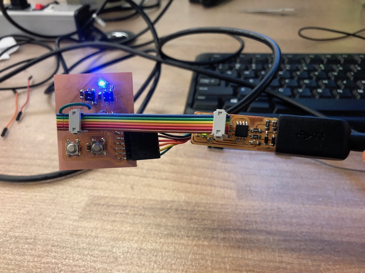
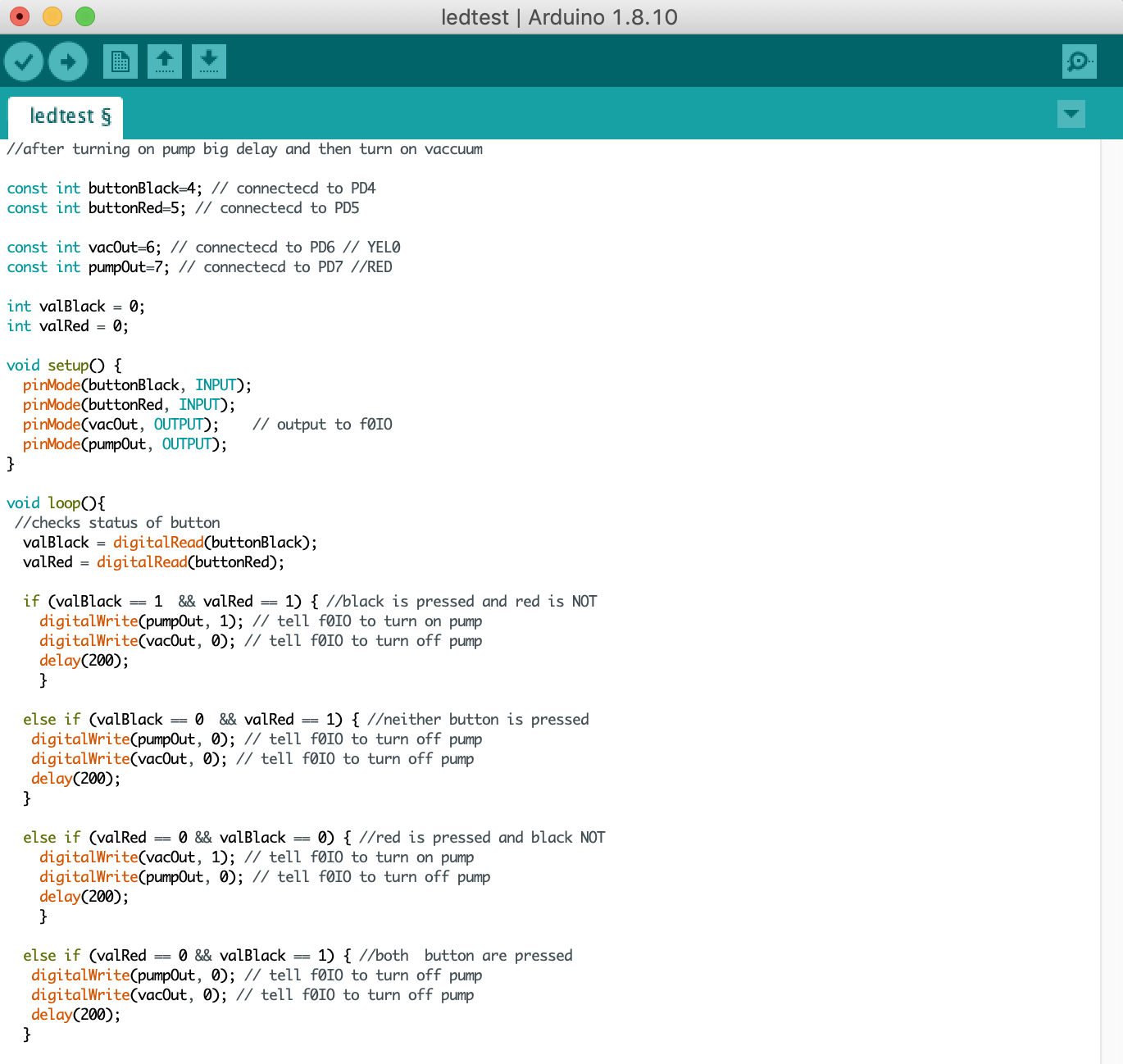
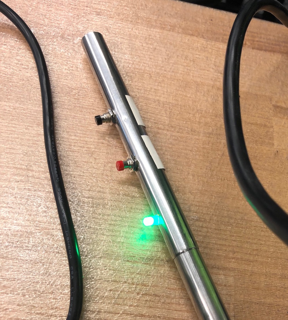
This was the code for my first test. This was just a simple code that would turn on an LED depending on what button is pressed. Also, to make sure my outpin pins were working themselves, I connected an LED to each of those pins to see if each LED would also light up aswell.
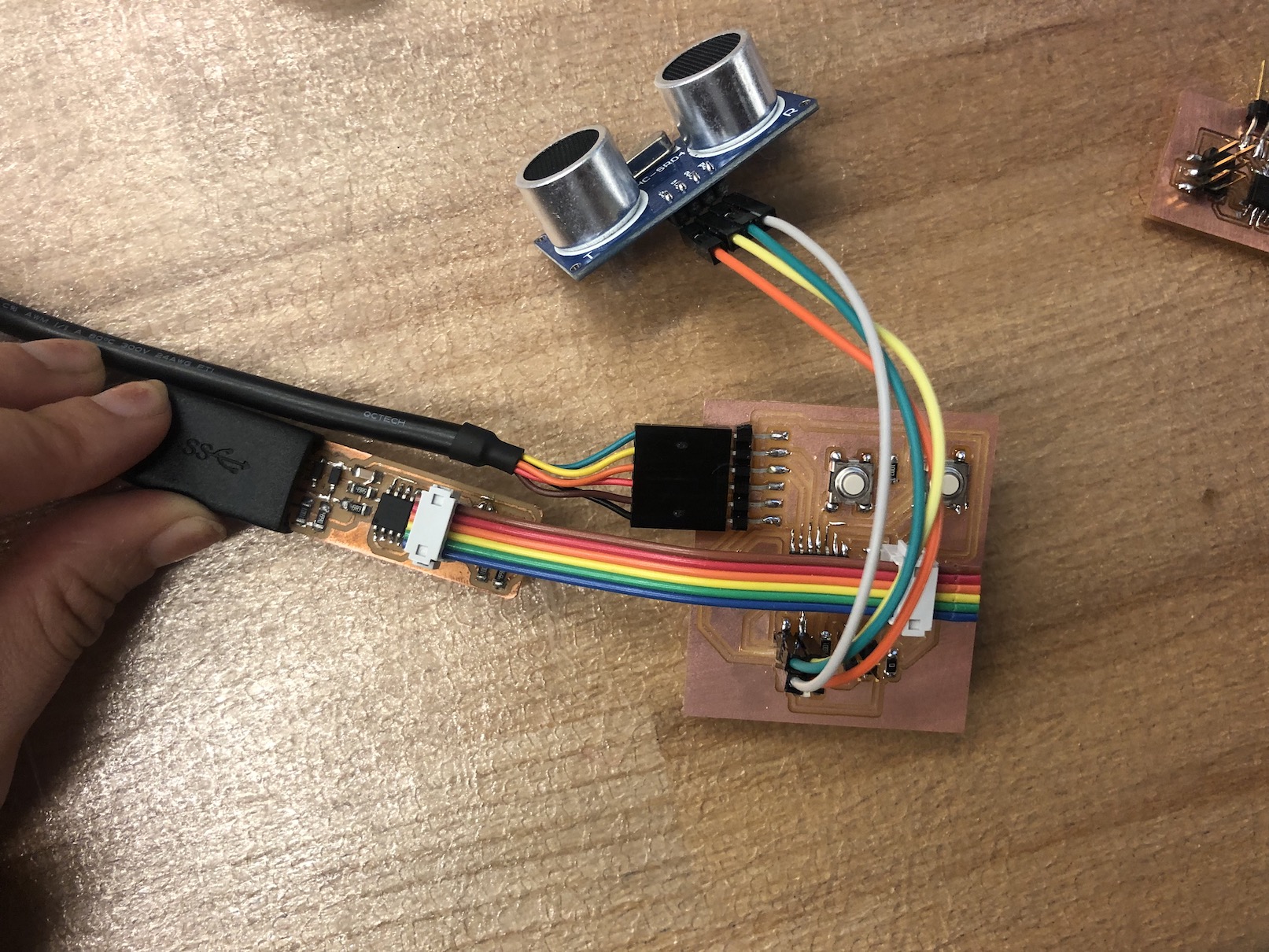
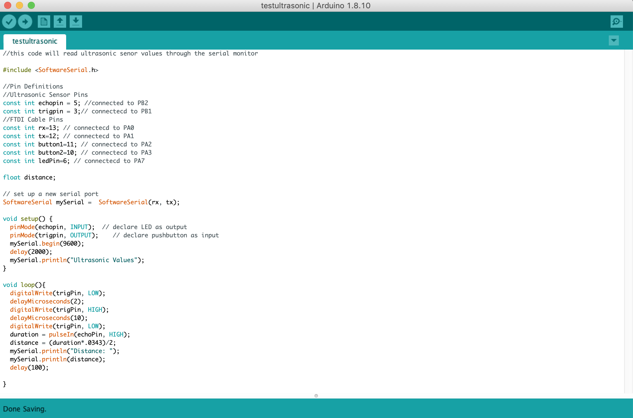
This code was for my second test of the ultrasonic sensor. I just wrote a simple code that would just use software serial to print the values that the Ultrasonic sensor was sensing.
Manual Mode
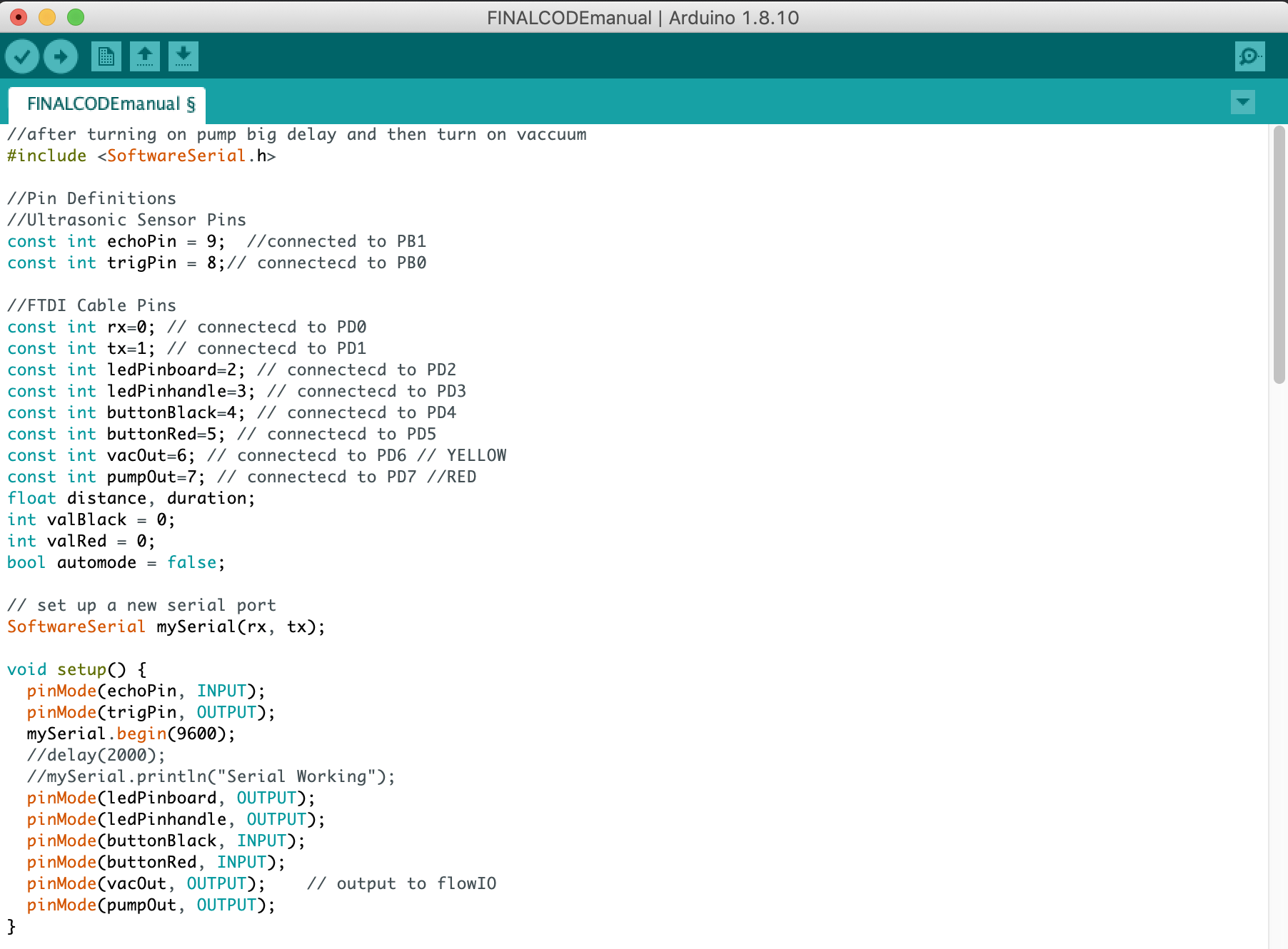
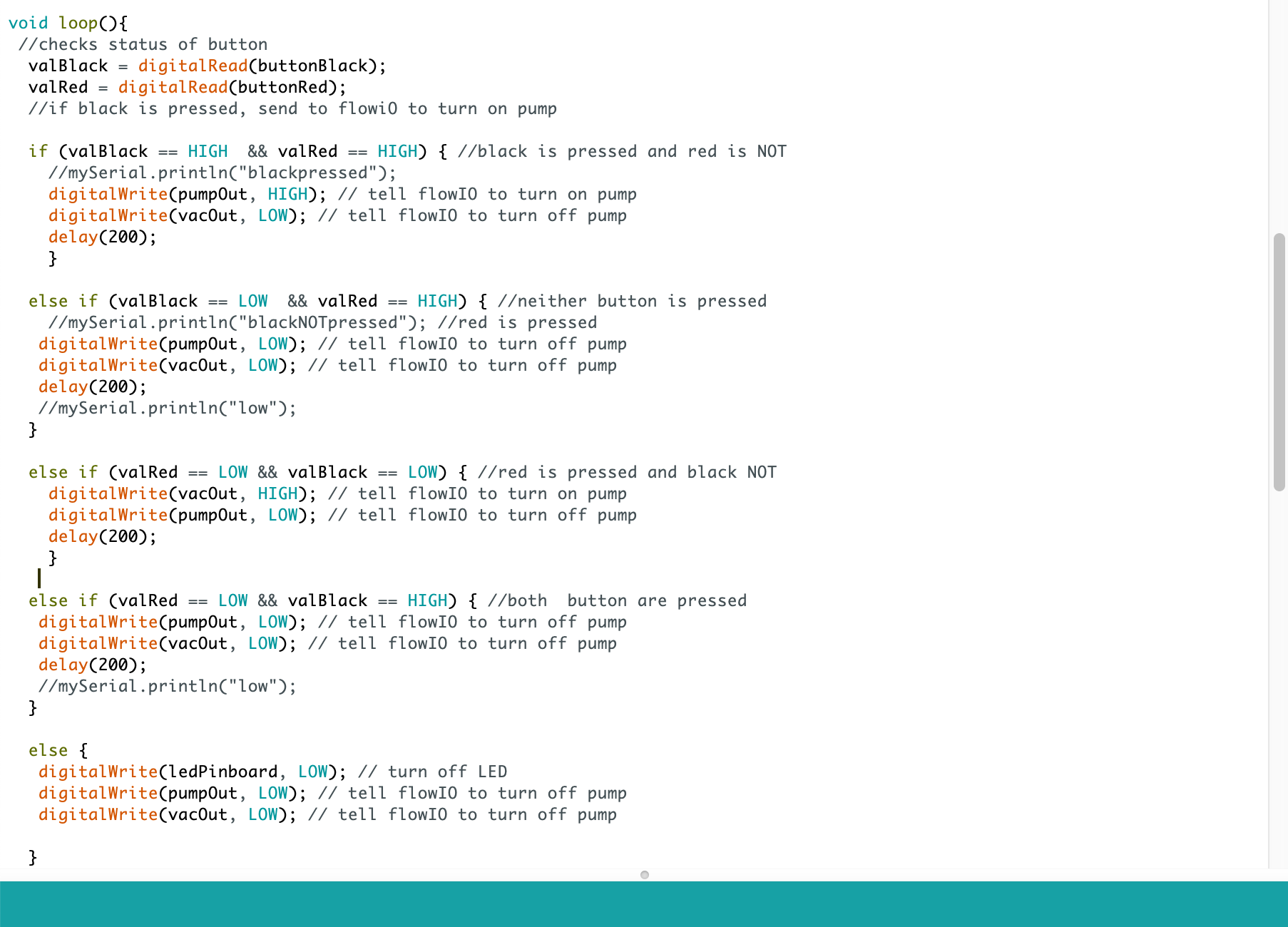
This was the final code for the manual mode of my Pneumatic gripper. How this script works is if a user pressed the red button on the gripper, this turns on the pump from the FlowIO and actuates the gripper motion. The pump only stays on if the button is pressed. Once a user finished grabbing an item, the black button starts the vacuumm and then the object is realeased.
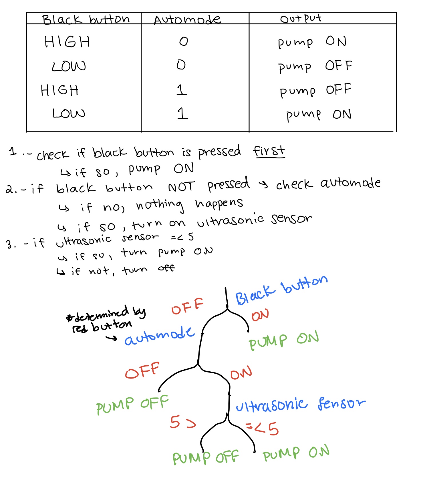
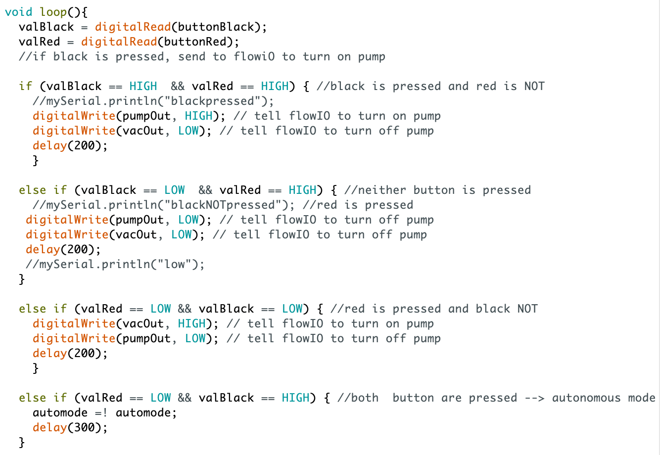
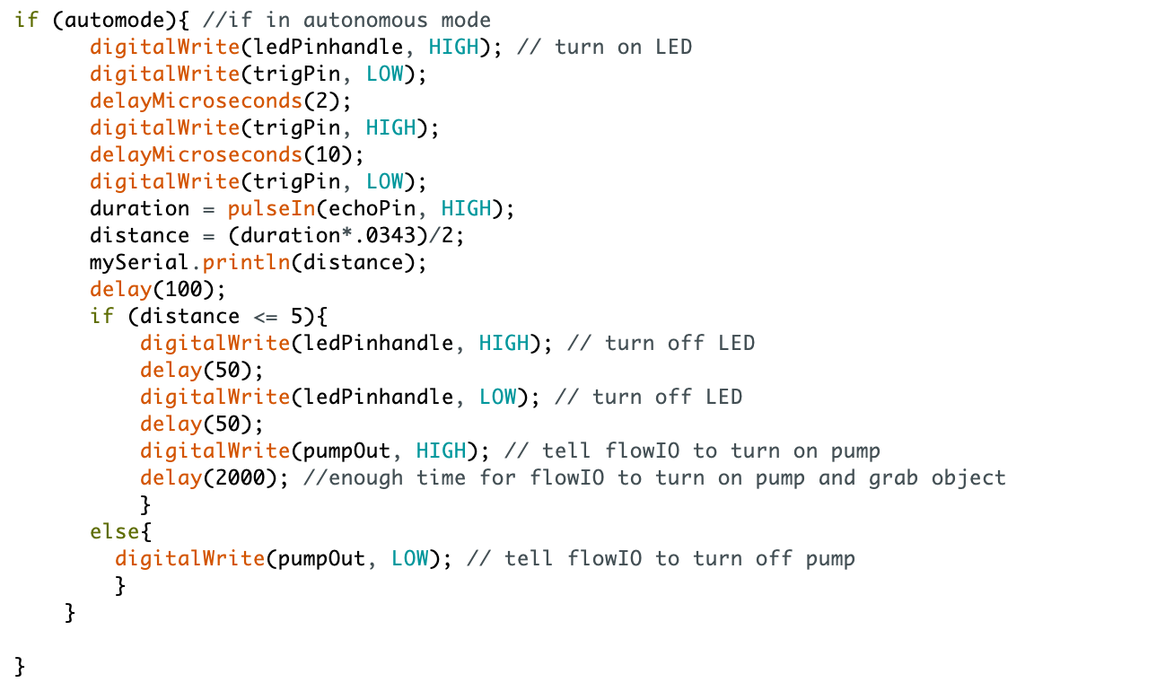
Autonomous Mode
The first thing I did before starting the code for autonomous mode was write down everything that I wanted to happen during autonomous mode. I found that it was best described with through a tree. At the end, the way that autonomous mode worked was if the black button is not being pressed (which would mean that manual mode is on), then the user would be able to long press the red button to enable autonomous mode. Then during autonomous mode, if the ultrasonic sensor reads a value under 5 cm, then that means there is an object within grabbable distance from the gripper. When this happens, the board tells the flowIO to turn on the pump for a certain amount of time. Then, when the red button is pressed again, autonomous mode is stopped and the gripper is back in manual mode.
Electronics and Gripper Housing
Parametrically Modeling Box
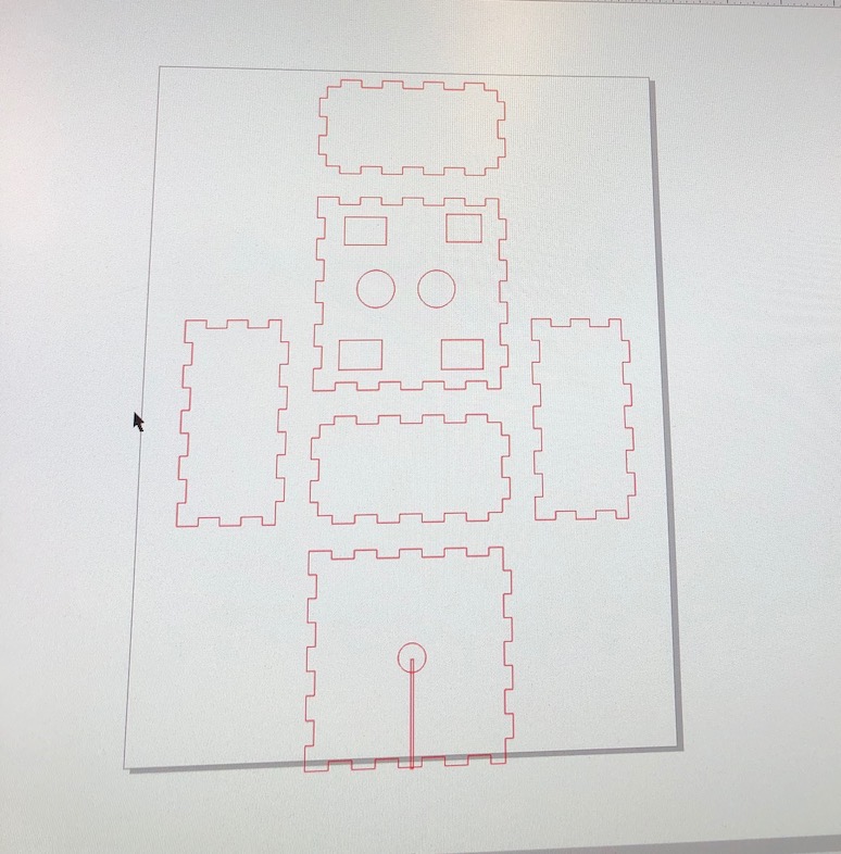
I designed the housing for the electronics and gripper parametrically. In my original design, I wanted to make a box where all of the electronics, including the FlowIO would be included. However, from my electronics design, I was going to supply power to all my electronics using the battery in the flowIO. Because of this, if anything ever went wrong where the pump wouldn't turn off, I needed to access the flowIO to turn off the device before my actuators would burst. This is a picture of my first design, where I didn't take into account where the electronics and tubing would leave the housing to attach to the flowIO. In my second model I added two more holes for the wires and tubing. Also, the way that I attached the grippers was through pressfit. After printing my first try of the housing and placing the grippers, I realized that all of the grippers were of different dimensions. Because of this, I used calapers to measure the dimentions of each gripper and change the dimensions of each of the rectangular openings on the top of the housing.
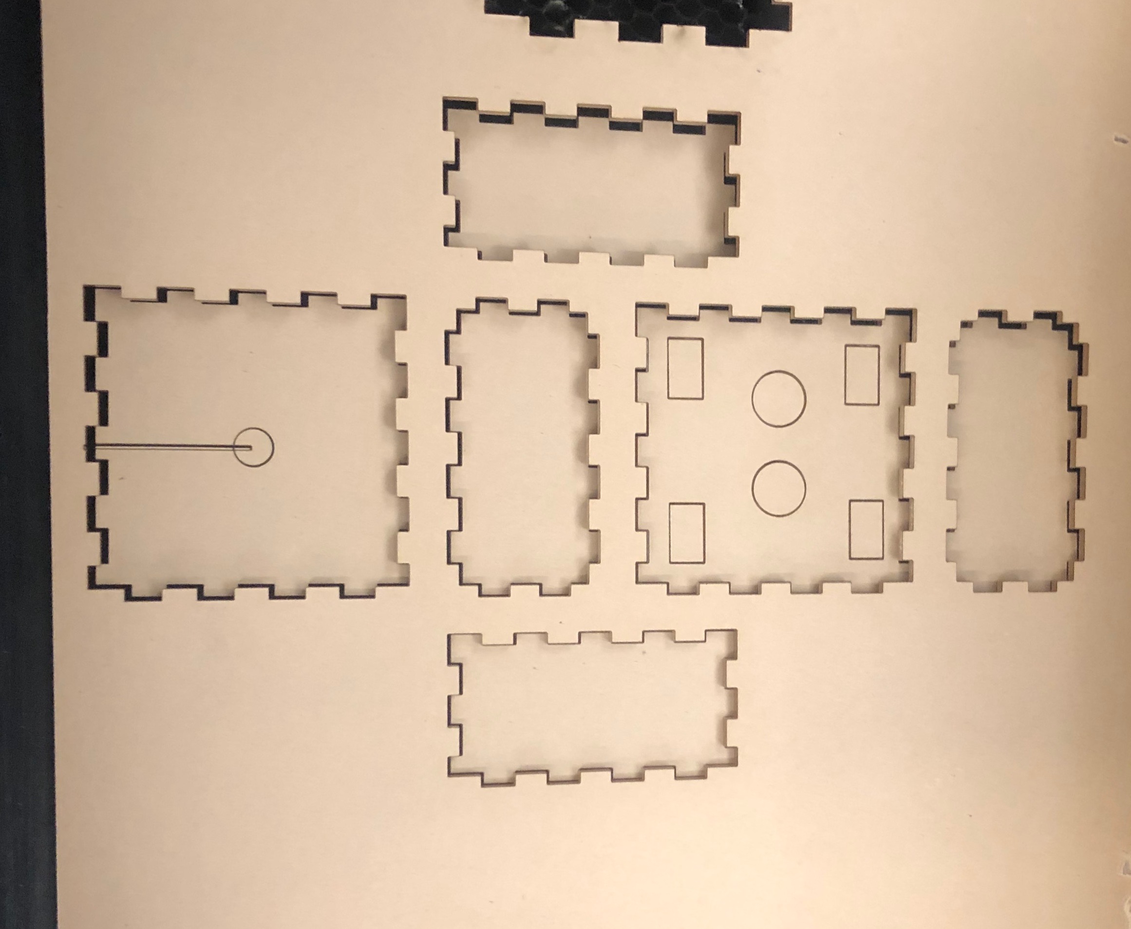
Lazer Cutting Acrylic
Assembled Housing
System Integration
The most important part of this process is finally integrating all of the various mechanical and electrical parts together. The following video displays the Pneumatic integration step by step as well as the autonomous mode integration testing.
Assemblying Electronics and Gripper Housing
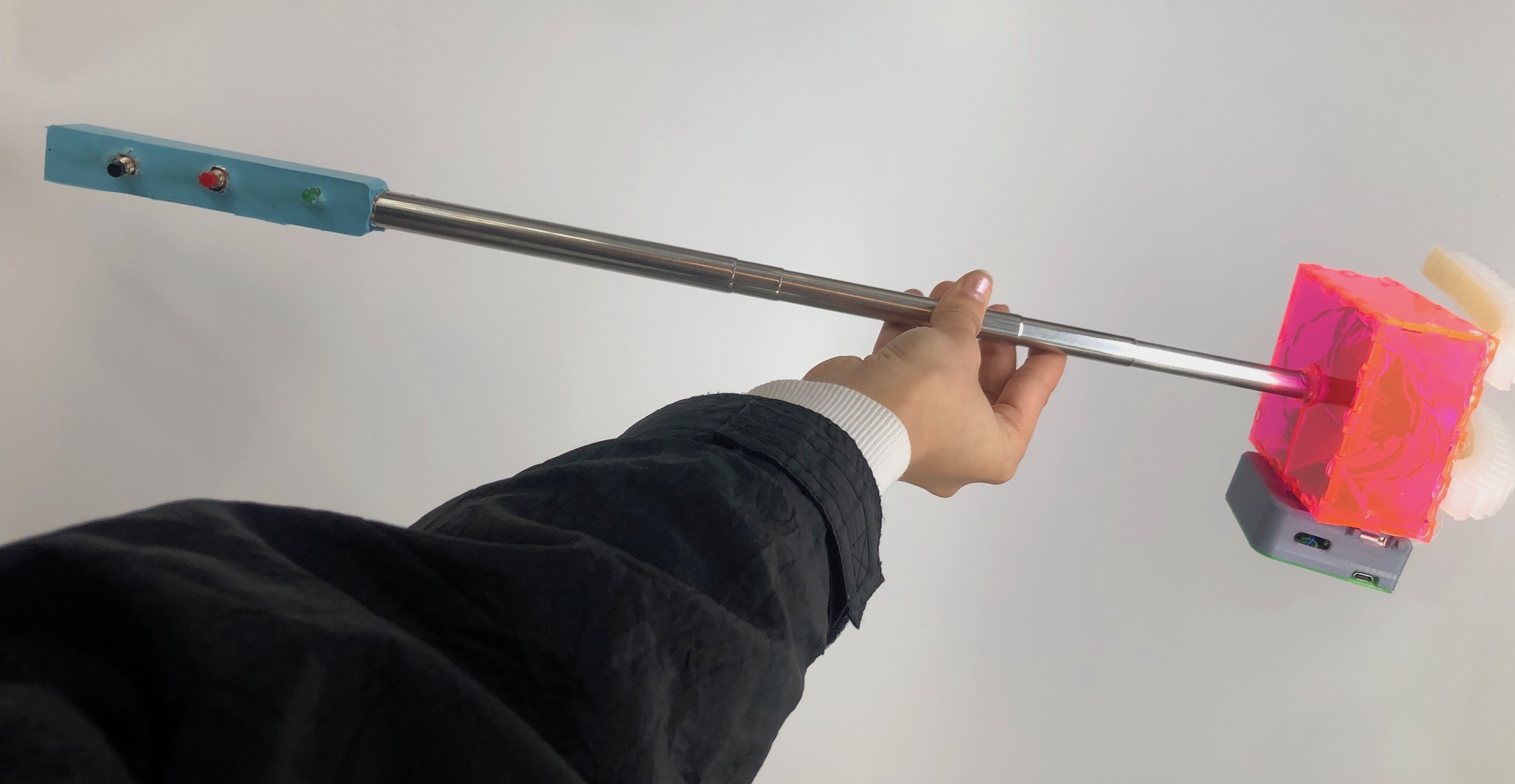
The thin opening on the base of electronic and gripper hosing allowed for the wires that were already inserted int he gripper to be placed within the housing. I then hot glued the base to the stick.
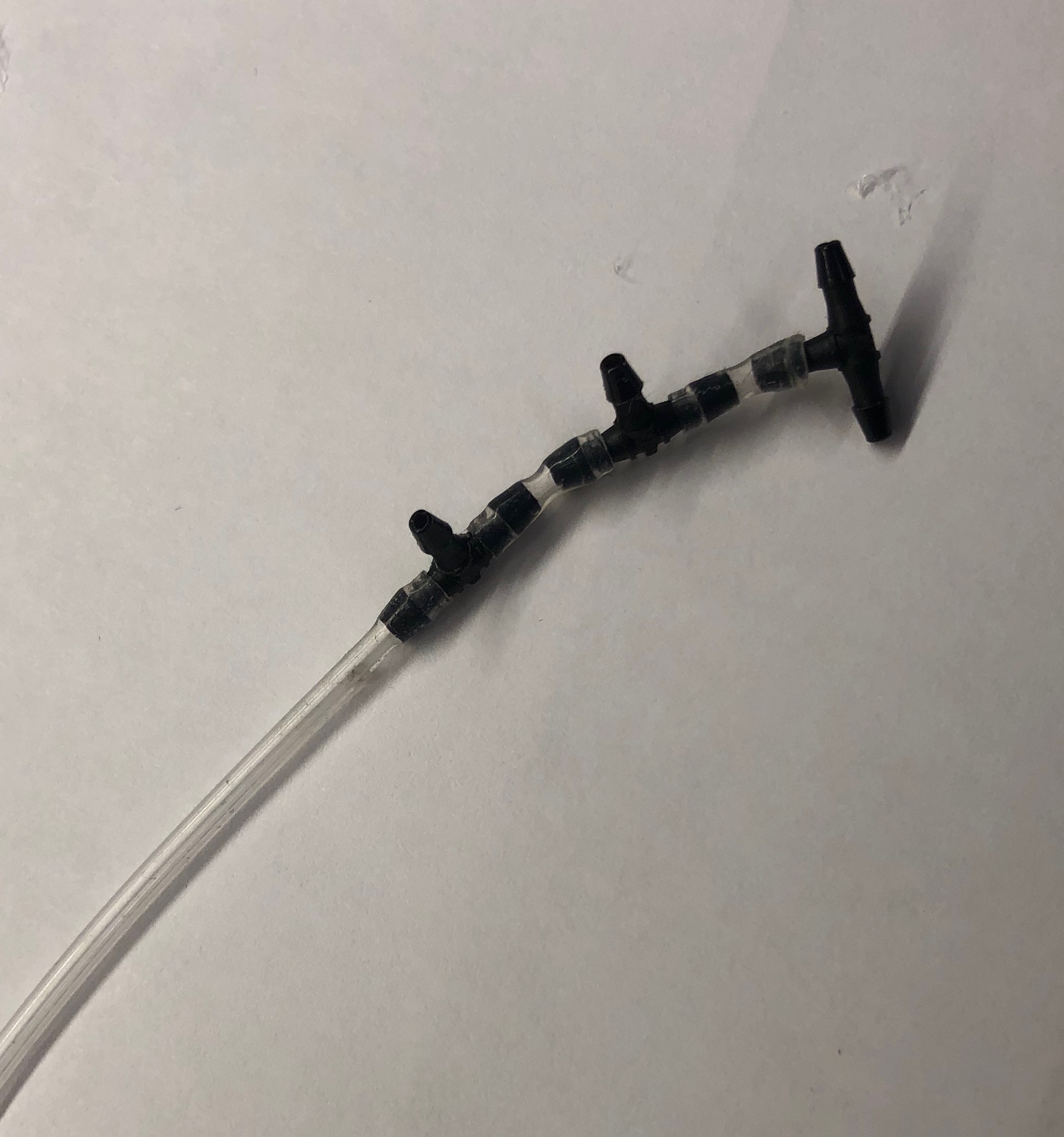
Because of power limitations of the small 3.3V lipo battery used in the flowIO, I was only able to use one of the ports for the flowIO to connect to all 4 of my grippers to make best use of the power. I found these valves that I was able to connect by cutting up small pieces of tubing and insterting them on the ends of the valves. Through this, I have one longer tube to connect to the flowIO and then four valve openings to connect each of my grippers.
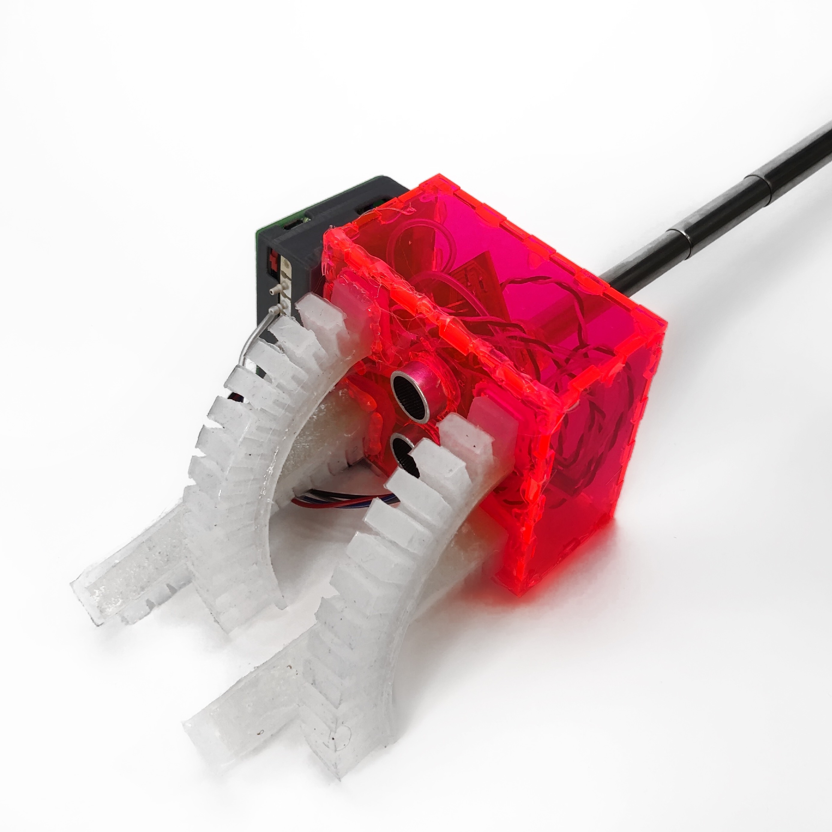
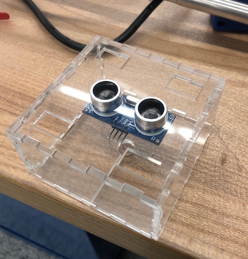
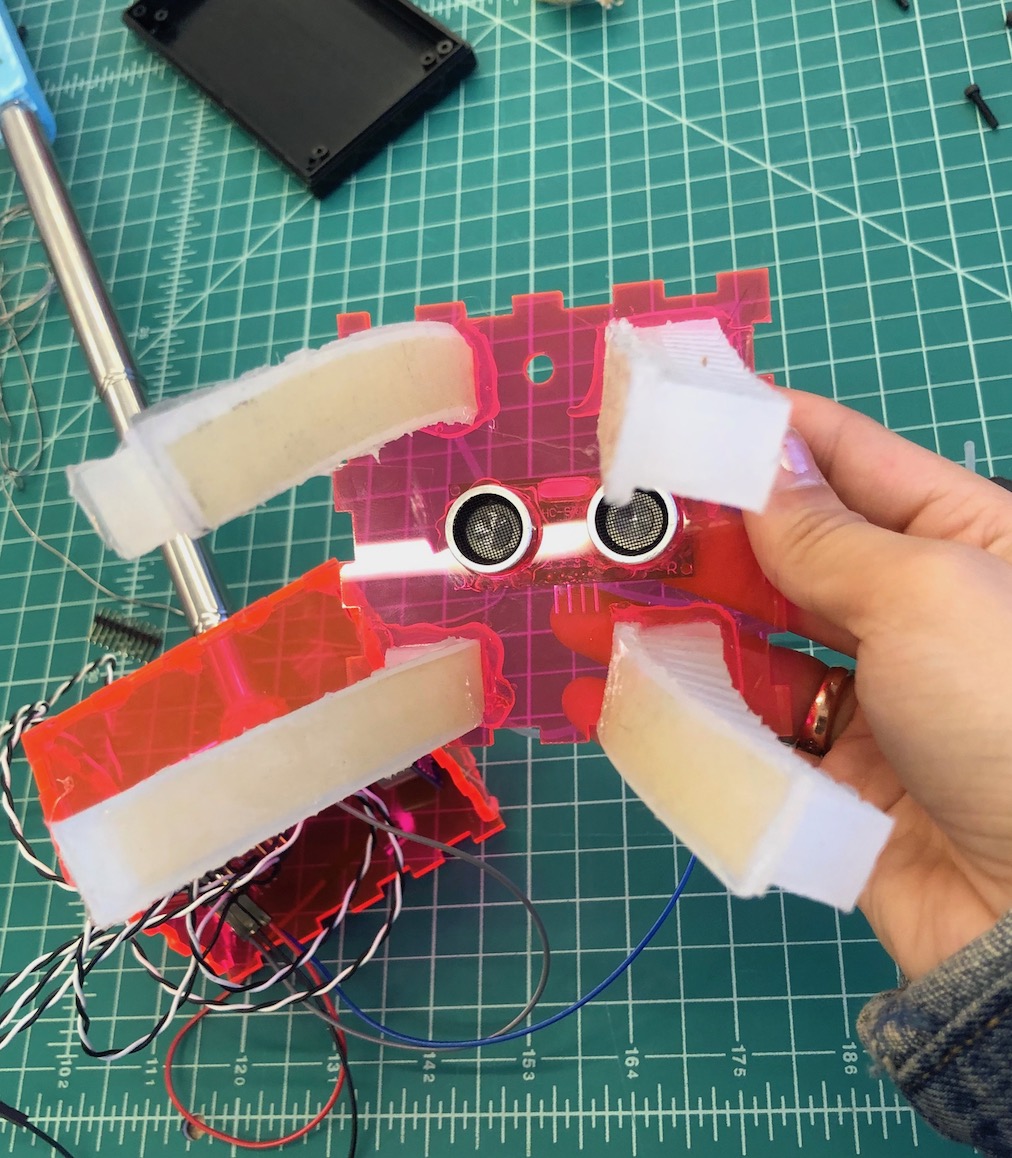
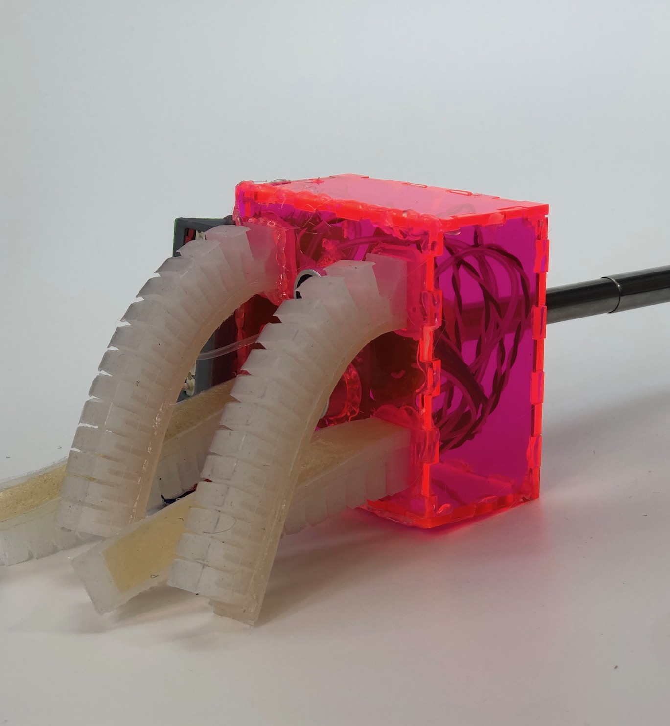
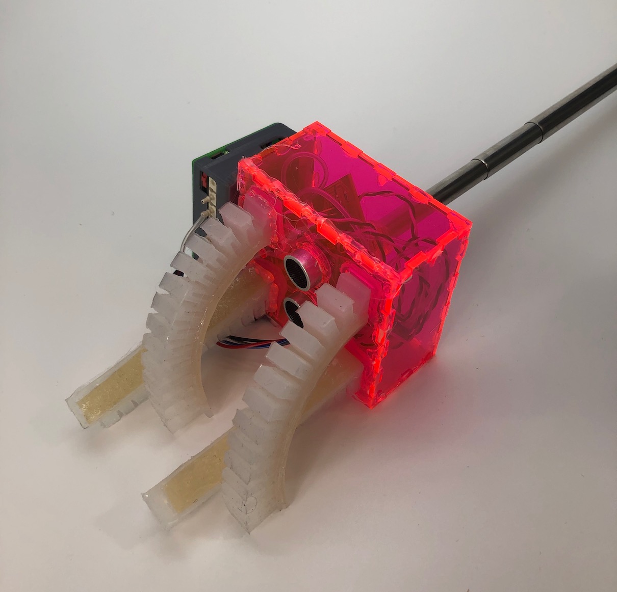
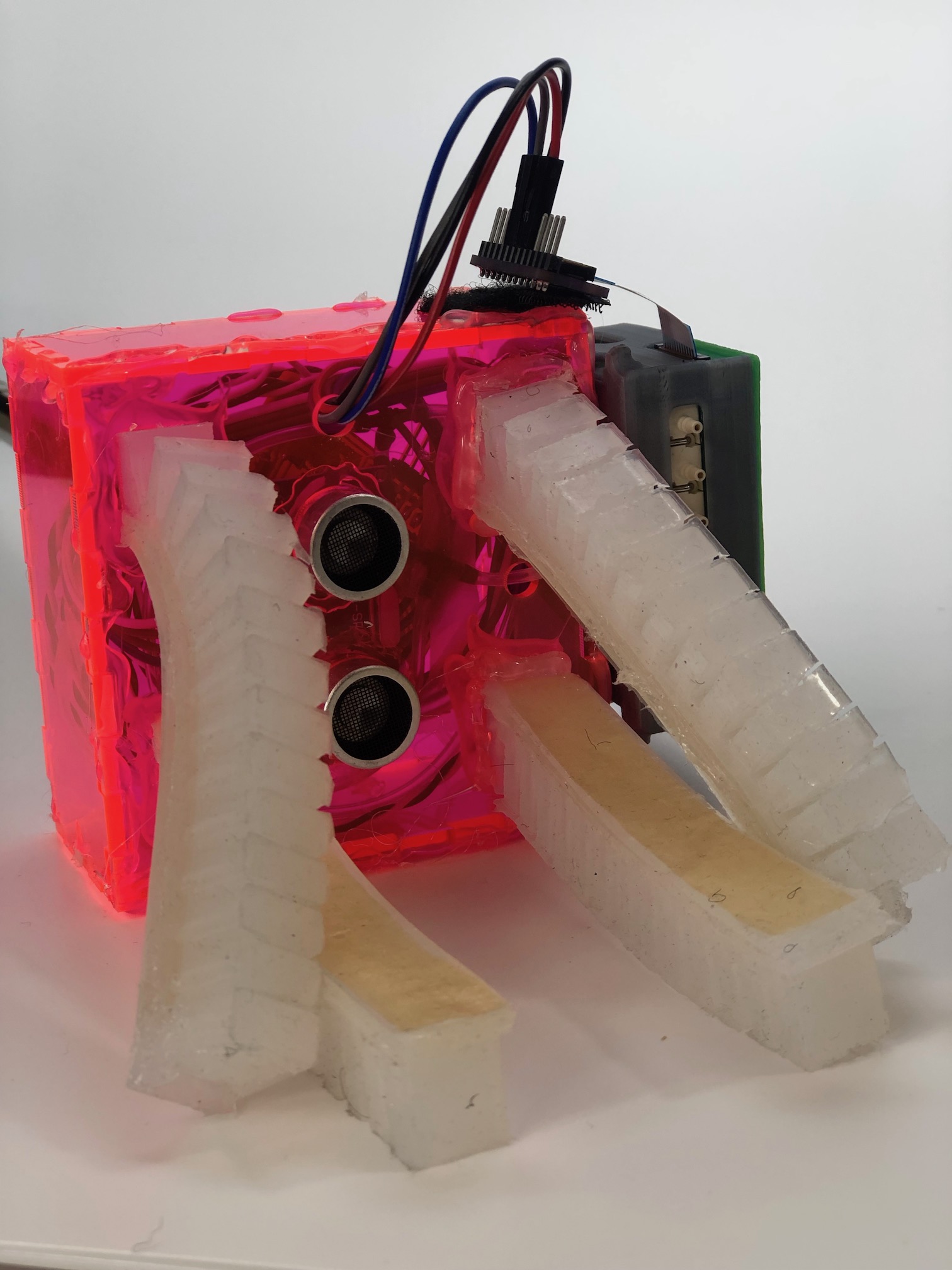
After creating custom dimensions for each of my grippers, I was able to easily pressfit all of the grippers to my housing. To secure the vertical motion of the grippers incase the handle was shaken vigorously, I used hotglue to secure the pressfit. If I had more time, I woul've used Sil-Poxy to secure the grippers to the housing. I also hot glued the ultrasonic sensor to the front aswell.
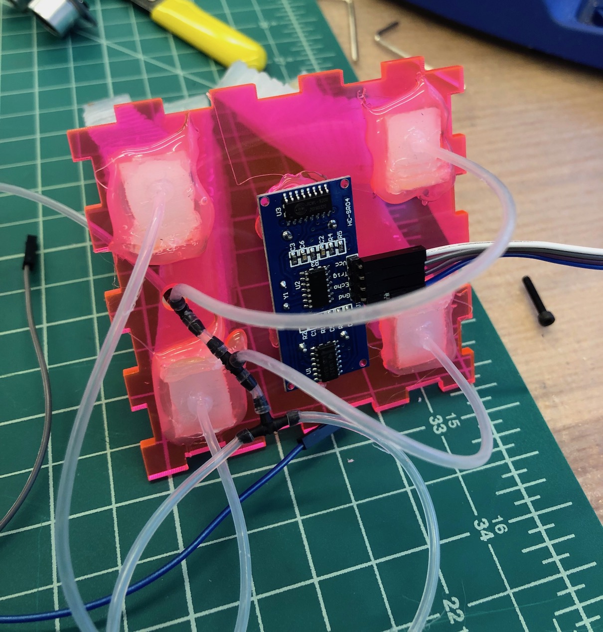
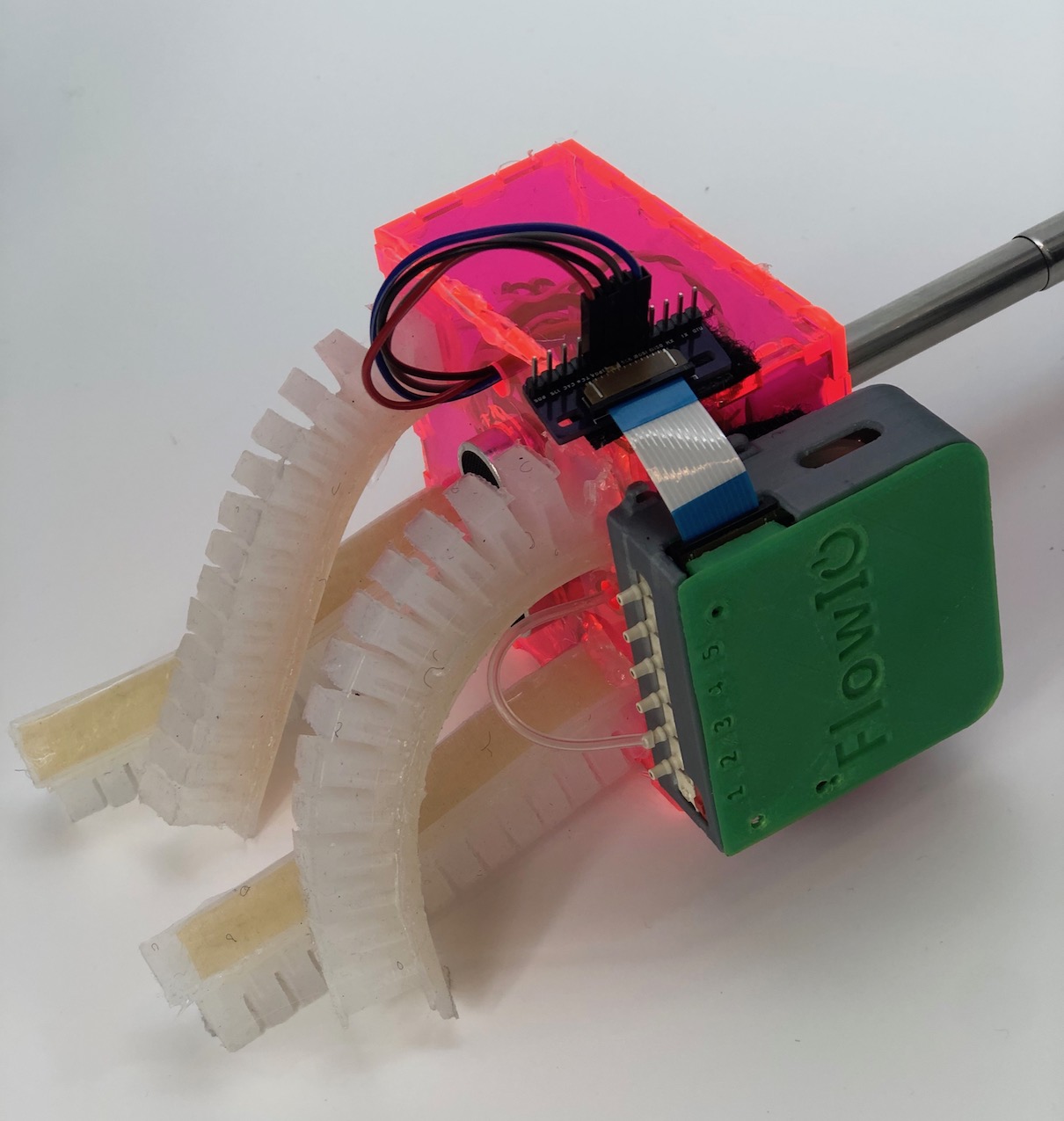
This is the backside of the front of the housing where you can see the tubing and wires come together.
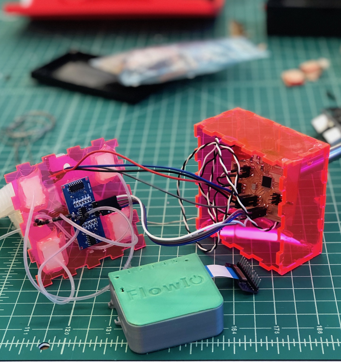
Integration Between the FlowIo and Board
To connect my board to the flowIO I needed four wires: ground, VCC, and two digital output pins to output to the FlowIO for the pump and vaccuum actions.
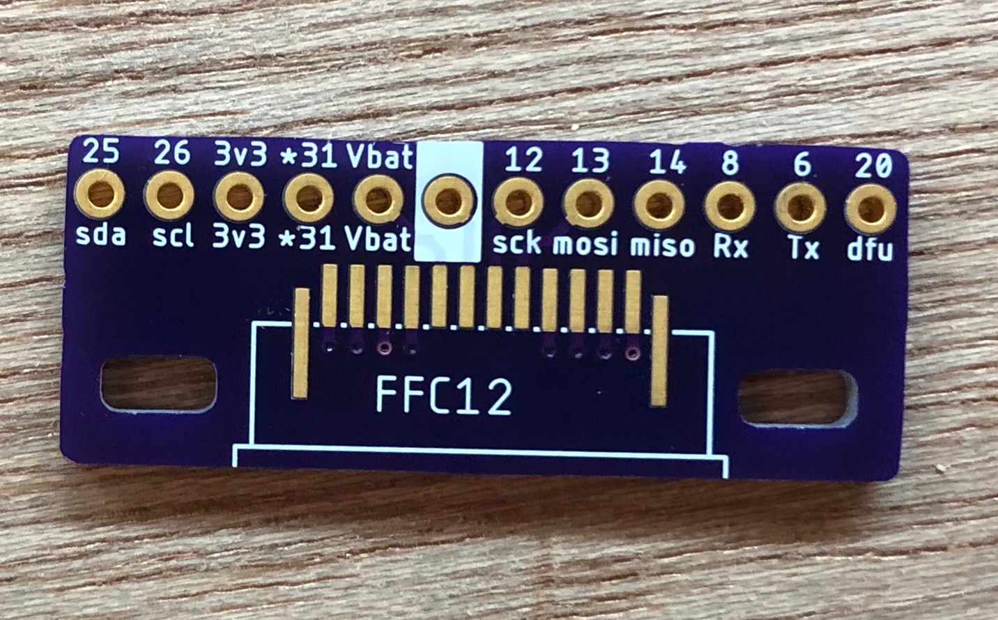
FlowIO Adapter
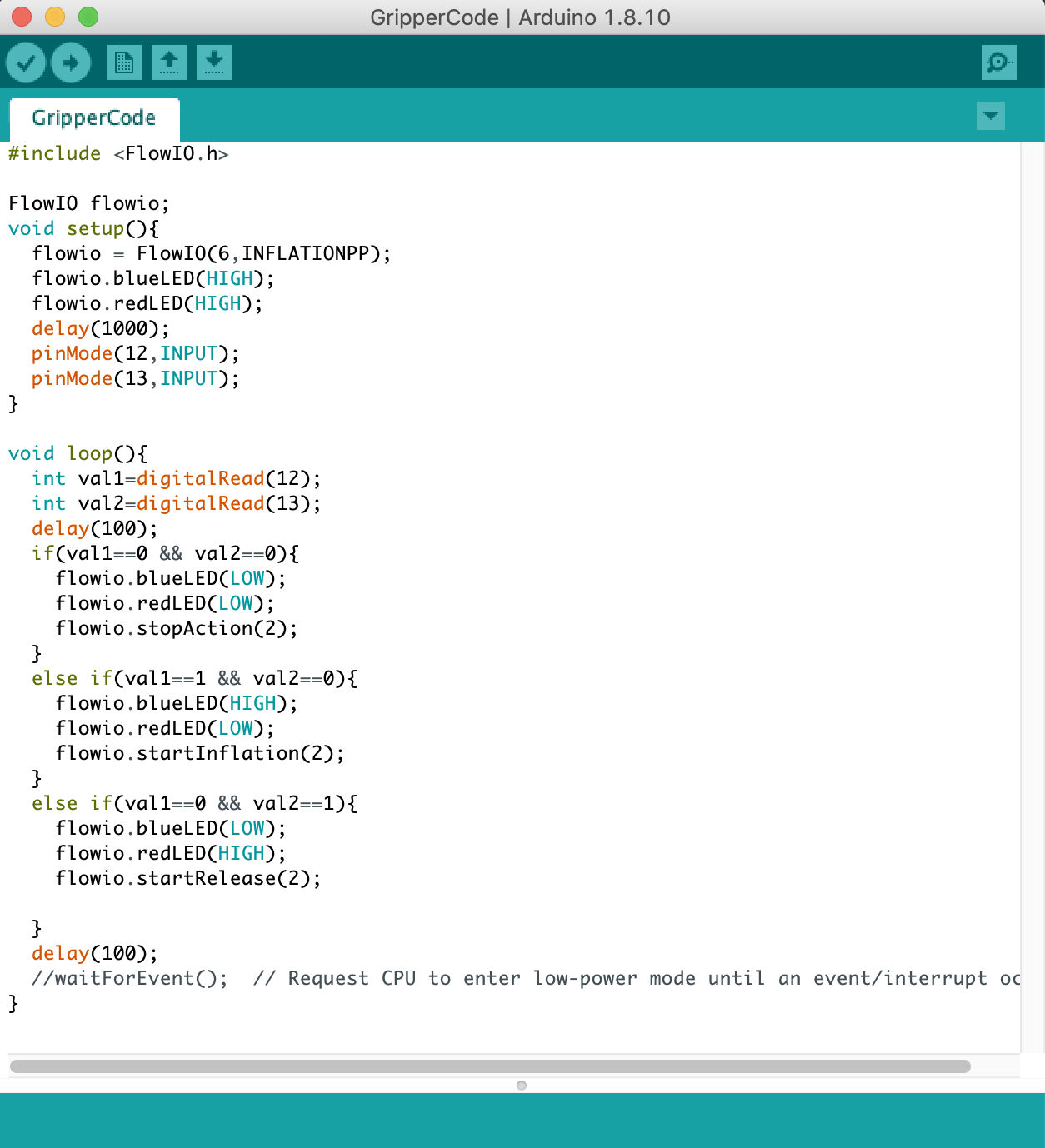
Programming the FlowIO
I programmed my board that I created to digitalWrite to two pins whenever the pump or vacuum needed to be turned on or off. I needed to program the flowIO to work with my other board by digitalReading the two pins that are connected from my board to the FlowIO and turning on the pump and vacuum accordingly. The FlowIO platform supports the following 4 pneumatic actions at each pneumatic IO port: Inflation, Vacuum, Relese, Pressure sensing (absolute pressure). In order to program the FlowIO, I used the FlowIO library. This is an Arduino-compatible library for controlling a pneumatic with N pneumatic ports and 2 pumps. By using the FlowIO library, the example above can be implemented with as little as 3 lines of code (if the high-level methods are used), or as many as 19 lines of code (if the low-level methods are used, or anything in between if a combination of high-level and low-level methods is used.
Integration Testing Setup
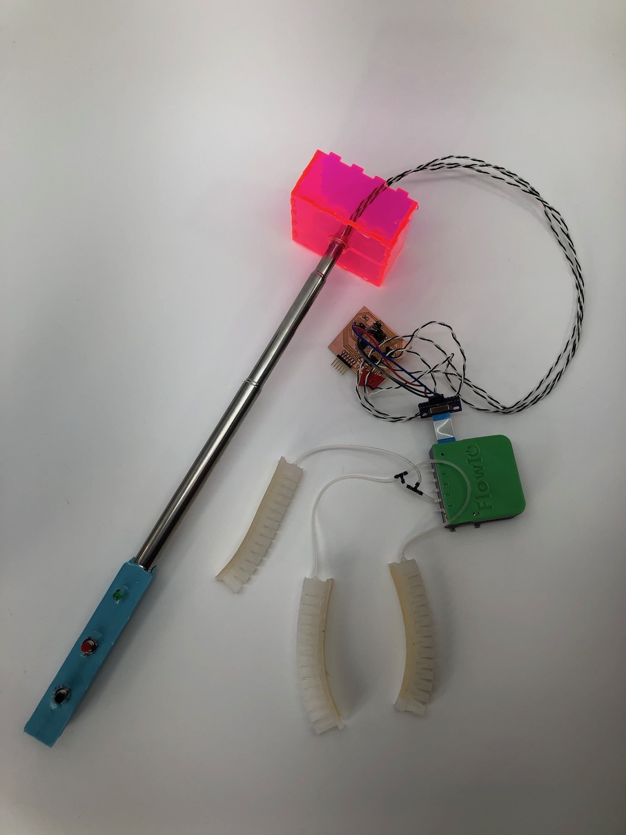
After this successful test, I know that everything was working properly and was able to put all of the electronics in the housing and hotglue everything shut to be a secure final project!
Final Product Photoshoot
At the end, I had an amazing time in this class and I learned so much and now I truly belive I'm one step closer in being able to make almost anything :)

Similar Projects
Click below to explore more of my projects!