Being able to define shapes to be drawn in the context of an OpenGL ES view is the first step in creating your high-end graphics masterpiece. Drawing with OpenGL ES can be a little tricky without knowing a few basic things about how OpenGL ES expects you to define graphic objects.
This lesson explains the OpenGL ES coordinate system relative to an Android device screen, the basics of defining a shape, shape faces, as well as defining a triangle and a square.
Define a Triangle
OpenGL ES allows you to define drawn objects using coordinates in three-dimensional space. So,
before you can draw a triangle, you must define its coordinates. In OpenGL, the typical way to do
this is to define a vertex array of floating point numbers for the coordinates. For maximum
efficiency, you write these coordinates into a ByteBuffer, that is passed into the
OpenGL ES graphics pipeline for processing.
class Triangle {

    private FloatBuffer vertexBuffer;

    // number of coordinates per vertex in this array
    static final int COORDS_PER_VERTEX = 3;
    static float triangleCoords[] = { // in counterclockwise order:
         0.0f,  0.622008459f, 0.0f,   // top
        -0.5f, -0.311004243f, 0.0f,   // bottom left
         0.5f, -0.311004243f, 0.0f    // bottom right
    };

    // Set color with red, green, blue and alpha (opacity) values
    float color[] = { 0.63671875f, 0.76953125f, 0.22265625f, 1.0f };

    public Triangle() {
        // initialize vertex byte buffer for shape coordinates
        ByteBuffer bb = ByteBuffer.allocateDirect(
                // (number of coordinate values * 4 bytes per float)
                triangleCoords.length * 4);
        // use the device hardware's native byte order
        bb.order(ByteOrder.nativeOrder());

        // create a floating point buffer from the ByteBuffer
        vertexBuffer = bb.asFloatBuffer();
        // add the coordinates to the FloatBuffer
        vertexBuffer.put(triangleCoords);
        // set the buffer to read the first coordinate
        vertexBuffer.position(0);
    }
}
By default, OpenGL ES assumes a coordinate system where [0,0,0] (X,Y,Z) specifies the center of
the GLSurfaceView frame, [1,1,0] is the top right corner of the frame and
[-1,-1,0] is bottom left corner of the frame. For an illustration of this coordinate system, see the
OpenGL ES developer
guide.
Note that the coordinates of this shape are defined in a counterclockwise order. The drawing order is important because it defines which side is the front face of the shape, which you typically want to have drawn, and the back face, which you can choose to not draw using the OpenGL ES cull face feature. For more information about faces and culling, see the OpenGL ES developer guide.
Define a Square
Defining triangles is pretty easy in OpenGL, but what if you want to get a just a little more complex? Say, a square? There are a number of ways to do this, but a typical path to drawing such a shape in OpenGL ES is to use two triangles drawn together:
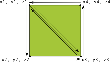
Figure 1. Drawing a square using two triangles.
Again, you should define the vertices in a counterclockwise order for both triangles that
represent this shape, and put the values in a ByteBuffer. In order to avoid
defining the two coordinates shared by each triangle twice, use a drawing list to tell the
OpenGL ES graphics pipeline how to draw these vertices. Here’s the code for this shape:
class Square {

    private FloatBuffer vertexBuffer;
    private ShortBuffer drawListBuffer;

    // number of coordinates per vertex in this array
    static final int COORDS_PER_VERTEX = 3;
    static float squareCoords[] = { -0.5f,  0.5f, 0.0f,   // top left
                                    -0.5f, -0.5f, 0.0f,   // bottom left
                                     0.5f, -0.5f, 0.0f,   // bottom right
                                     0.5f,  0.5f, 0.0f }; // top right

    private short drawOrder[] = { 0, 1, 2, 0, 2, 3 }; // order to draw vertices

    public Square() {
        // initialize vertex byte buffer for shape coordinates
        ByteBuffer bb = ByteBuffer.allocateDirect(
        // (# of coordinate values * 4 bytes per float)
                squareCoords.length * 4);
        bb.order(ByteOrder.nativeOrder());
        vertexBuffer = bb.asFloatBuffer();
        vertexBuffer.put(squareCoords);
        vertexBuffer.position(0);

        // initialize byte buffer for the draw list
        ByteBuffer dlb = ByteBuffer.allocateDirect(
        // (# of coordinate values * 2 bytes per short)
                drawOrder.length * 2);
        dlb.order(ByteOrder.nativeOrder());
        drawListBuffer = dlb.asShortBuffer();
        drawListBuffer.put(drawOrder);
        drawListBuffer.position(0);
    }
}
This example gives you a peek at what it takes to create more complex shapes with OpenGL. In general, you use collections of triangles to draw objects. In the next lesson, you learn how to draw these shapes on screen.